crwdns2915892:0crwdne2915892:0
Your camera's motherboard, the main system circuit board which processes inputs and produces outputs, is essential to system operation. This guide will teach you how to access and remove the D5100's motherboard.
crwdns2942213:0crwdne2942213:0
-
-
Remove the five screws around the camera using a Phillips #00 screwdriver.
-
-
-
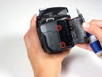
Use your fingernail to gently peel back the black rubber thumb grip, attached to the chassis with a strong adhesive.
-
Use the Phillips #00 to remove the screw underneath the black rubber grip.
Note: you don't need to peel it off completely. Peel it just enough to expose the screw. Afterwards you can put the rubber thumb grip back and it'll stick to camera body pretty well (looking as new), unless maybe if you've done this lots of times.
-
-
-
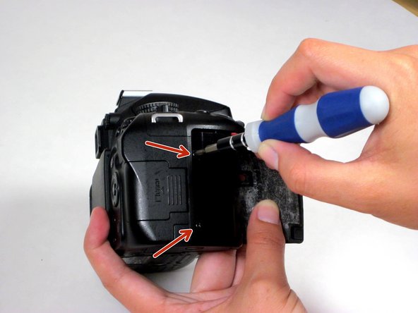
Carefully peel back the black rubber hand grip, which is attached to the chassis with a strong adhesive.
-
Use the Phillips #00 to remove two screws beneath the handgrip.
When reassembling the camera back together, how do I put back parts attached by adhesive? Will they stick back on their own? Will I need to use some glue?
Warning: these two screws are made from a different material than most of the other ones. They're quite fragile and prone to the screw head wearing out. You don't want that to happen! Make sure you use a good quality screwdriver and apply enough pressure so that your screwdriver doesn't "slide" and damage the screw head.
About the rubber grip: most of its corners fit tightly to the surrounding camera body so it's mostly ok when you assemble this back. However, my grip's corners do look a bit worn out and not fully attached to the body, after several camera disassemblies.
-
-
-
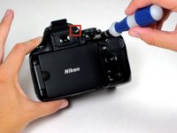
Using a spudger, pry off the diopter adjustment dial cover and remove the screw underneath.
-
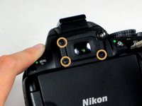
Next, using a Phillips #00 screwdriver, remove the three Phillips screws around the viewfinder.
Spudgers didn't work well for me for removing the dial cover. I only ended up scratching it. What worked for me is a small sharp knife.
-
-
-
Carefully separate the rear panel from the camera body.
Make sure SD card section cover doesn't fall out! I had that happen and it's incredibly hard and frustrating to put it back!
-
-
-
-
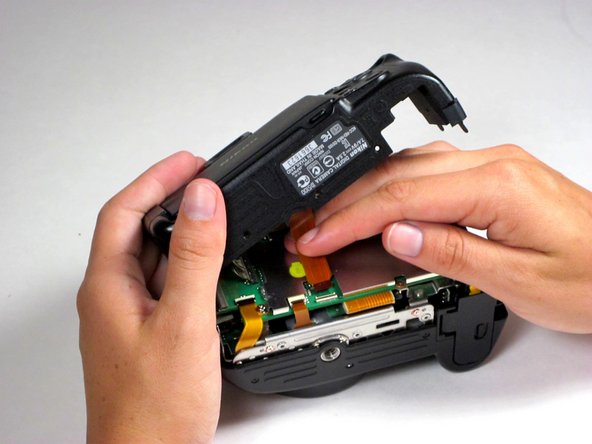
Remove the dark orange ribbon cable attaching the rear panel to the motherboard by flipping the black plastic clasp up, away from the motherboard, and pull the cable out of its white casing in the direction of the cable.
-
-
-
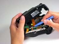
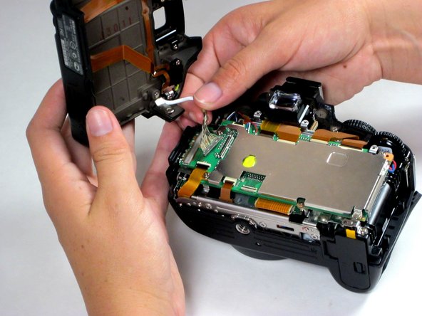
Remove the silver 16-pin cable by pulling gently upwards, away from the inside of the camera, until it separates from its port.
-
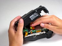
At this point, the rear panel is fully separated from the main body of the camera.
This is the 40 pin cable for the display and reconnecting this cable may not be as straight forward as described !
-
-
-
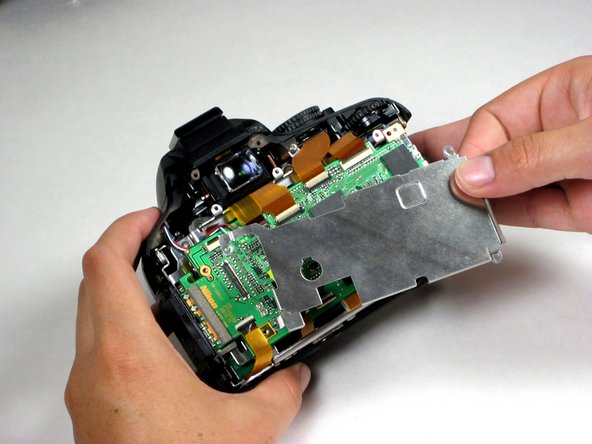
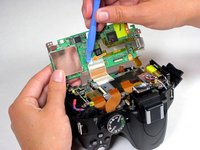
Use a Phillips #00 screwdriver to remove the five screws holding the motherboard cover plate. Starting with the right side, lift the plate and remove it from the camera body. Set the plate aside.
-
-
-
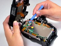
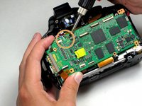
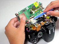
Located on top of the motherboard, there are six dark orange ribbon cables. Flip the black plastic lock at each cable up to unlock the cable. Pull the cables straight back away from the white connector to release it.
There's actually 7 dark orange ribbon cables. One of them is already removed on these pictures. It's in the top left corner of the motherboard.
-
-
-
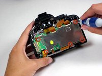
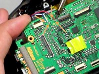
Using a spudger, slide underneath the twisted red and blue cables and gently pull away from the camera body. This will disconnect them from the motherboard.
-
-
-
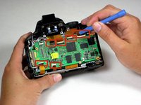
Desolder the black, white, blue, and red wires that are fixed to the upper left-hand portion of the motherboard.
-
-
-
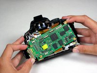
Flip the motherboard out of the camera's body, toward the bottom of the device, to expose its underside.
-
Using a spudger, peel back the adhesive, that is protecting the large ribbon cable on the underside of the motherboard.
-
Disconnect the ribbon cable by flipping its clasp up and removing it from the plastic casing in the direction of the cable.
-
-
-
The motherboard is now free of all connections to the camera. Remove it from the camera body.
-


To reassemble your device, follow these instructions in reverse order.
To reassemble your device, follow these instructions in reverse order.
crwdns2935221:0crwdne2935221:0
crwdns2935229:015crwdne2935229:0
crwdns2915084:0crwdne2915084:0

Cal Poly, Team 10-54, Amido Spring 2014 crwdns2935289:0Cal Poly, Team 10-54, Amido Spring 2014crwdne2935289:0
CPSU-AMIDO-S14S10G54
crwdns2931471:04crwdne2931471:0
crwdns2935297:05crwdne2935297:0
crwdns2947412:04crwdne2947412:0
Thanks for the guide. I would not have attempted this without your help.
After replacing the main board, the only issue I am having is that the top focus point is not lighting up when I select it. It still works as a focus point, but is not light in the view finder as red. I probably did not perfectly seat one of the ribbon cables. It would be nice if someone new which cable controlled lighting in red the focus dots in the viewfinder.
Thanks so much!
Hey David, where did you get the new mainboard from? Know of any website that sells them? I need one for D5000. Thanks!
pbmbuss -
ebay seller from chicago area has tons of nikon parts
rongyuanxie |
Feedback Score Of
128606 | 99.2%
(i'm not that seller)
Thanks a lot for this beautiful guide. My D5100 is fix now.