crwdns2915892:0crwdne2915892:0
Common Scanner Issues
Issue 1: High-Pitched Whirring Sound
- Scenario A: If you start the scanner without any adapter inserted, the start-up process will complete without any issues. However, when you insert the MA-20/21 adapter (or any other adapter), you will hear a loud, high-pitched whirring sound at the end of the adapter's initialization process.
- Scenario B: If you power up the scanner with the adapter already inserted, the main stepper motor will produce a loud, high-pitched whirring sound at the end of the startup process.
- Additional Note: Sometimes, after the loud whirring sound, the scanner may blink rapidly. This behavior is inconsistent and may or may not occur.
Issue 2: Offsett Scanned Images
- Observation: If the scanned images are offset along the long axis, it is likely due to either a gear slipping on the shaft of the main stepper motor or a gear slipping on the shaft of the main leadscrew. Link to example image.
Troubleshooting and Solutions
- Step 1: First, check for a slipping gear. This is often the root cause of the problem.
- Step 2: If the gear is not slipping, the issue is probably due to a main stepper motor failure.
Specific Model Note
- This type of failure is particularly common in late production models (SN4XXXXX) of the LS-50 and LS-5000 scanners.
- The replacement procedure for the stepper motor is relatively straightforward. However, sourcing a replacement motor is challenging since there are no new replacement motors available for purchase. You will need to salvage one from an old scanner/ebay. Stepper motors from LS-50, LS-5000, LS-40, and LS-4000 models are compatible.
This eBay link is regularly updated with new parts for sale, including the stepper motor mentioned in this guide.
crwdns2942213:0crwdne2942213:0
-
-
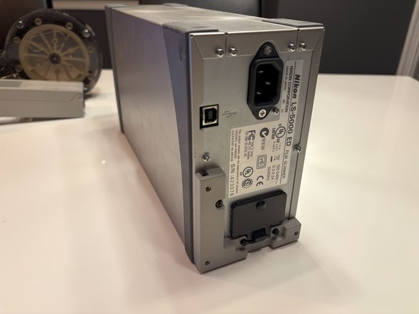
Disconnect Power Sources: Unplug both the power and USB cables from the sacnner.
-
Remove Accessories: Take out any adaptors or additional devices connected to the scanner.
-
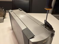
Position the Scanner: Carefully place the scanner upside down on a clean, flat surface, ensuring it is in a secure and stable position.
-
-
-
Locate the Screws: Identify the six screws positioned on the back of the unit.
-
Prepare Your Tools: Gather the appropriate screwdriver, ensuring it matches the screw heads to avoid damage.
-
Unscrew Carefully: One by one, remove each of the six screws by turning them counterclockwise. Make sure to keep them in a safe place for reassembly.
-
Inspect the Unit: Once all screws are removed, gently check the back of the unit to ensure it is ready for further steps in the disassembly process.
-
-
-
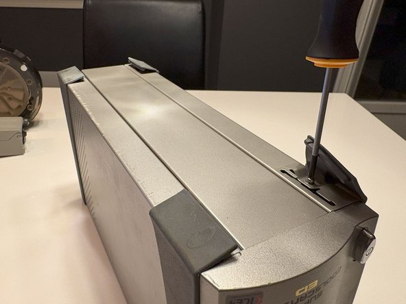
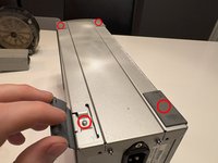
Locate the Rubber Pads: As indicated by the red arrow above, find the four rubber pads positioned at the corners on the bottom of the scanner.
-
Remove the Pads: Gently pull out each rubber pad to expose the screws beneath them.
-
Prepare Your Tools: Ensure you have the appropriate screwdriver for the screws.
-
Unscrew: Carefully remove the four screws by turning them counterclockwise. Keep them safe for reassembly.
-
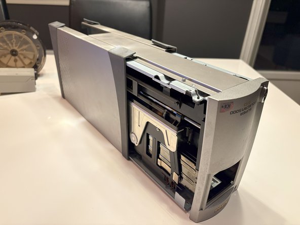
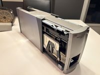
Remove the Shell: Once the screws are removed, gently slide the metal shell off the scanner, revealing the internal components.
-
-
-
-
Identify the Screws: Locate the six screws marked by red circles in the diagram or image provided.
-
Prepare Your Tools: Ensure you have the correct screwdriver for the screws.
-
Unscrew: Carefully turn each screw counterclockwise until it is fully removed. Keep these screws in a safe place for reassembly.
-
Remove the Bottom Plate: Once all six screws are out, gently lift and remove the bottom metal plate from the unit, exposing the components beneath it.
-
-
-
Identify the Plastic Tab: Locate the plastic tab that needs to be pried.
-
Prepare to Pry: Use a suitable prying tool, such as a plastic spudger or a flathead screwdriver, to avoid causing any damage.
-
Pry Carefully: Gently insert the tool under the plastic tab and apply light pressure to lift it. Take your time and be gentle to avoid breaking the tab.
-
Remove the Front Plate: Once the tab is pried open, slowly take the front plate off the unit.
-
Handle with Care: Keep in mind that the tabs are fragile and can easily break, so proceed with caution throughout the process.
-
Please note that, as shown in the picture, the tabs on my scanner are broken due to the actions of a previous owner. Therefore, exercise caution when removing them to avoid damage
-
-
-
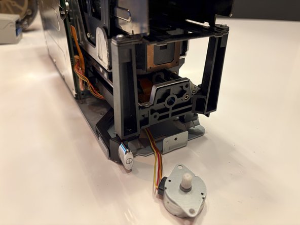
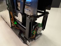
Locate the Stepper Motor: With the front plate removed, you will now have a clear view of the main stepper motor.
-
Identify the Screws: Find the two screws marked by green circles that are securing the stepper motor in place.
-
Prepare Your Tools: Ensure you have the appropriate screwdriver to safely remove these screws.
-
Remove the Screws: Carefully unscrew each of the two screws by turning them counterclockwise. Keep these screws in a safe place for reassembly.
-
Disconnect the Connector: Locate the connector marked by the green arrow. Gently pull the connector by the wires, applying a slight wiggling motion to free it.
-
Handle with Care: Be gentle throughout this process to avoid damaging the wires or the connector.
-
-
-
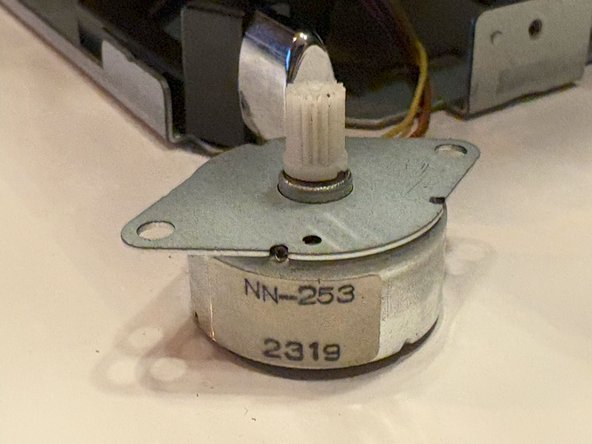
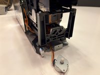
Examine the Motor: Refer to the photo above to see the motor with its gear removed. Notably, in this instance, the gear slipped off effortlessly because it was cracked as shown in the photo.
-
Assess Gear Condition: If the gear isn't cracked but just loose, follow the next steps to secure it properly.
-
Clean the Components: Thoroughly clean both the gear and the shaft to ensure there is no dirt, grease, or debris that could affect the adhesion.
-
Apply Adhesive: Place a drop of superglue on the shaft where the gear sits. Ensure you use a small amount to avoid excess glue seeping out.
-
Reattach the Gear: Carefully place the gear back onto the shaft, aligning it properly. Press gently to ensure it sits securely in place.
-
Allow to Set: Give the superglue some time to dry and set fully before proceeding with any further reassembly or use of the motor.
-


To reassemble your device, follow these instructions in reverse order.
crwdns2935221:0crwdne2935221:0
crwdns2935227:0crwdne2935227:0
