crwdns2915892:0crwdne2915892:0
If your Nikon Coolpix P4 does not turn on after charging it or replacing the battery, you may need to replace the motherboard. This guide will tell you how to replace your Nikon Coolpix P4 motherboard.
The motherboard is what operates communications between the different parts of the camera. It is also what controls the entire camera. A faulty or broken motherboard will prevent your camera from working.
Before beginning, make sure you have a new motherboard ready to replace the old one, turn off your camera, make sure it's not plugged into the charger, and remove the battery.
crwdns2942213:0crwdne2942213:0
-
-
Flip the camera upside down (have the side with the buttons facing away from you)
-
Look for the side with the triangle icon with three lines in it, this is the battery door. Add pressure and slide this door slightly until it clicks and pops open.
-
-
-
Once the door clicks, you can open it to reveal the slots holding the memory card and the battery.
-
Focusing on the larger slot, this holds the battery. Push the orange tab away from the slot, this will eject the old battery if one was previously inside.
-
Once this slot is open, you can place the new battery inside.
-
-
-
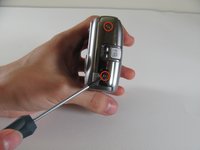
Remove the four 2.2 mm screws located on the bottom of the camera.
-
-
-
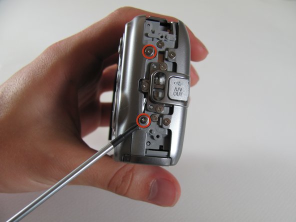
Remove the two 2.9 mm screws from the side panel.
-
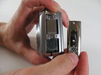
Remove the side panel.
-
-
-
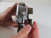
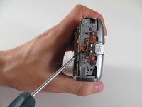
Remove the two 5 mm screws from the right side panel.
-
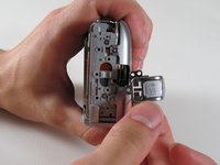
Remove the panel from the right side.
-
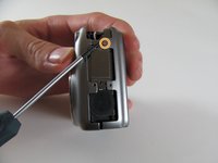
Remove the single 2.1 mm screw set underneath the panel.
-
-
-
Remove the two 4.8 mm screws attaching the back panel to the body on the left side.
-
-
-
Remove the three 4.8 mm screws from the A/V out tab on the left side.
-
Remove the tab.
-
-
-
Remove the two 4.6 mm screws attaching the front panel to the body on the left side.
-
-
-
-
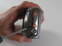
Remove the 2.2 mm screw.
-
Remove the 2.9 mm screw.
-
Remove the 2.1 mm screw.
-
-
-
Carefully pull the orange LCD connector up and out of the port.
-
-
-
Remove the 3.1 mm screw below the LCD.
-
-
-
Carefully pull out the plug connecting the LCD to the motherboard.
-
-
-
Remove the LCD from the camera body.
-
-
-
Remove the two screws on the opposite sides of the flash.
-
-
-
Remove the two 2.9 mm screws on the right side of the camera.
-
-
-
Remove the four screws on the bottom of the camera.
-
-
-
Remove the seven 2.8 mm screws from the back of the camera.
-
-
-
Detach the cable that connects the lens to the left side of the motherboard.
-
-
-
Remove the 2.8 mm screw from the top of the camera.
-
-
-
Remove the three 2.8 mm screws from the motherboard.
-
Detach the orange tab with the foam on top.
-
-
-
Remove the motherboard by pulling it up and out of the port.
-
-
-
Carefully remove the tab that connects the flash to the motherboard from the port by gently pulling the connector to the right and out of its port.
-
-
-
Fully remove the motherboard from the camera body.
-


To reassemble your device, follow these instructions in reverse order.
To reassemble your device, follow these instructions in reverse order.
crwdns2915084:0crwdne2915084:0

Cal Poly, Team 8-5, Regan Spring 2011 crwdns2935289:0Cal Poly, Team 8-5, Regan Spring 2011crwdne2935289:0
CPSU-REGAN-S11S8G5
crwdns2931471:04crwdne2931471:0
crwdns2935297:010crwdne2935297:0