crwdns2915892:0crwdne2915892:0
If you encounter issues with your camera motherboard, follow this step by step guide to aid you on replacing it.
crwdns2942213:0crwdne2942213:0
-
-
There are six screws attaching the back housing to the camera. Remove the screws from the body with a PH000 screw head.
-
Two 1.5x2.5mm screws on the right side.
-
Two 1.5x2.5mm screws on the underside.
-
Two 1.5x2.5mm screw on the left side.
-
-
-
After removing the screws, use a metal spudger or plastic opening tool to push the back cover out.
-
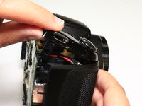
Remove the back housing of the camera by lifting it directly up.
-
-
-
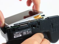
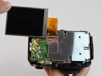
Insert the tips of your fingers into the space between the screen and back-plate.
-
Gently lift the screen up and out of the frame.
-
-
-
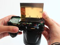
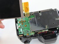
Tilt the screen so that the display cable forms a hinge with the backplate.
-
Rotate the display 180 degrees so that it faces you.
-
-
-
-
Using a plastic opening tool or fingernail, pop up the black clip holding the display cable. This will release the cable.
-
Slide the display cable out of the connector.
-
-
-
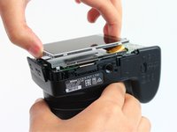
Remove the screws from the silver back-plate with a PH000 screw head.
-
Two 1.5x2.5mm screws on the left side.
-
One 1.5x2.5mm screw on the right side.
-
-
-
Remove the screws holding the motherboard with a PH000 screw head.
-
Two 1.5x2.5mm screws on the right side.
-
-
-
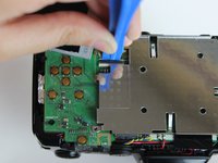
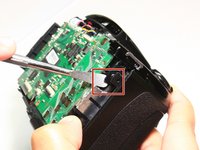
Using a plastic opening tool or fingernail, pop up the black clips holding the ribbon cables. This will release the cables.
-
Slide the ribbon cables out of the connectors.
-
-
-
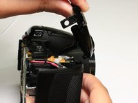
Remove the black sticker covering the electrical connections.
-
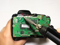
Desolder the eight wires from the motherboard.
-
-
-
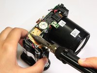
Insert a plastic opening tool into the marked position. Push the tool towards the right to release the clip.
-
Using a thumb and forefinger, push the plastic cover up until it is at a 45 degree angle.
-
Pull the cover back and up to release it.
-
-
-
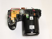
The motherboard is still held in place by soldered connections.
-
Carefully desolder the connections .
-
-
-
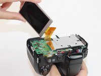
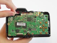
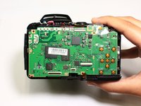
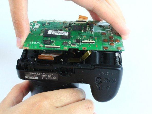
Remove the motherboard by lifting it directly up.
-


To reassemble your device, follow these instructions in reverse order.
To reassemble your device, follow these instructions in reverse order.
crwdns2935221:0crwdne2935221:0
crwdns2935227:0crwdne2935227:0
crwdns2915084:0crwdne2915084:0

USF Tampa, Team 2-10, Cagle Spring 2016 crwdns2935289:0USF Tampa, Team 2-10, Cagle Spring 2016crwdne2935289:0
USFT-CAGLE-S16S2G10
crwdns2931471:04crwdne2931471:0
crwdns2935297:014crwdne2935297:0