crwdns2915892:0crwdne2915892:0
In this guide, we will give you step-by-step instructions on how to remove the logic board so that it can be replaced or repaired.
crwdns2942213:0crwdne2942213:0
-
-
Remove the memory stick from the camera.
-
Remove the batteries from the camera.
-
-
-
Remove all six 4.3mm silver screws along the perimeter of the camera using the Phillips #00 screwdriver.
-
There is one screw hidden under the AV cover that also needs to be removed.
-
-
-
Pry the back cover from the left side of the camera. Remove the cover gently.
-
-
-
Pry back the front cover of the camera starting from the right side.
-
-
-
Remove the tape on the right side of the LCD screen.
-
Gently lift the LCD screen from its base.
-
-
-
Lift the black latch connecting the LCD ribbon to the motherboard.
-
Gently pull the LCD ribbon out.
-
-
-
-
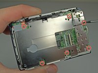
Remove the 6 Phillips #00 screws anchoring the LCD base to the motherboard.
-
Remove the LCD base plate.
-
-
-
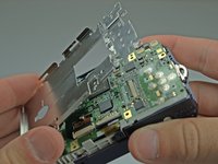
Lift the black latch connecting the LCD ribbon to the motherboard.
-
Gently pull the lens ribbon out.
-
-
-
Desolder the connection of the motherboard to the lens ribbon using a soldering iron and desoldering wick.
-
-
-
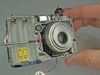
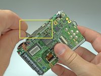
Lift up the black and copper covering on the left side of the camera.
-
-
crwdns2935267:0crwdne2935267:0Tweezers$4.99
-
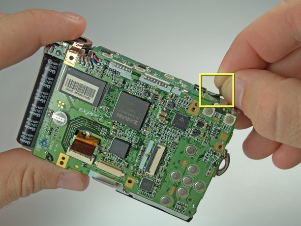
Pull the wiring at the top right of the camera away from the lens with tweezers.
-
-
-
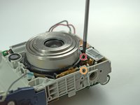
Remove the cross-hair shaped wire cap to the left of the lens.
-
-
-
Remove the 3 screws holding the lens to the camera frame.
-
Two 3.8mm black Phillips #00 screws on the sides of the lens.
-
One 4.6mm silver Phillips #00 screw on the bottom of the lens.
-
-
-
There is a screw behind flash tube holding lens. Remove it, then gently pull the lens out. Be sure that the lens's ribbon clears the motherboard.
-
-
-
Remove the tape on the top of the logic board.
-
-
-
Remove the 4 Phillips #00 screws holding the top of the logic board onto the camera frame.
-
-
-
Desolder the joint of the top and back of the logic board using a soldering iron and desoldering wick.
-
-
-
Move the top of the logic board to the side, exposing the top of the frame.
-
Desolder the two connections on the top right of the logic board using a soldering iron and desolering wick.
-


To reassemble your device, follow these instructions in reverse order.
To reassemble your device, follow these instructions in reverse order.
crwdns2935221:0crwdne2935221:0
crwdns2935229:03crwdne2935229:0
crwdns2915084:0crwdne2915084:0

Cal Poly, Team 9-23, Regan Fall 2010 crwdns2935289:0Cal Poly, Team 9-23, Regan Fall 2010crwdne2935289:0
CPSU-REGAN-F10S9G23
crwdns2931471:04crwdne2931471:0
crwdns2935297:010crwdne2935297:0