crwdns2915892:0crwdne2915892:0
The motherboard is the key component to making the camera run. If there is a faulty connection, the camera will not turn on at all. This repair should be completed with care, as to not interrupt the flow of power.
crwdns2942213:0crwdne2942213:0
-
-
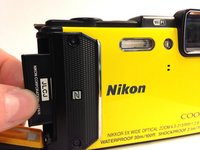
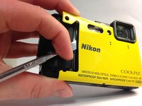
Using your thumb and pointer finger, open the card/battery hatch by pressing the center button of the wheel and turning the entire wheel to the left.
-
-
-
You should feel the door begin to loosen. Carefully pull the hatch open.
-
-
-
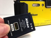
Push the yellow battery/charger compartment tab up using your thumb nail.
This yellow tab spring broken, how I can repair
From where I can get this yellow tab, and how I can replace
-
-
-
After pressing the yellow tab, the battery should loosen.
-
Slowly pull the battery completely out.
-
-
-
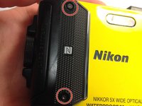
Using the T4 Torx Screwdriver, remove the 2, 4mm screws holding the N-Mark plate in place.
-
Carefully pull the plate off of the face.
ChK 2022_01_27: There is no need to remove the front panel in order to get to the main board. Skip this step.
-
-
-
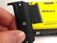
Using the metal spudger tool, pry the colored face from the camera body.
I think this step is unnecessary, and it´s very hard to take off this metal plate without damage
ChK 2022_01_27: There is no need to remove the front panel in order to get to the main board. Skip this step.
-
-
-
-
Using the T5 Torx screwdriver, remove all four 4mm screws.
-
-
-
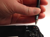
Using a Phillips #000 screwdriver, remove the single 3mm screw found inside the battery/charging compartment.
-
-
-
Remove the upper cover (connected by glue) and unscrew the single Philips screw.
Start with a metal spuge from the buckle on the lens-side and work your way from there.
Its not necessary to remove the whole thing - cause the side on the other buckle tends to break.
-
-
-
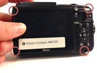
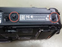
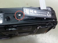
Remove two Philips screws from the bottom cover, lift gently the cover and remove the single Philips screw under it.
In the case of my camera, I had to move the plat that says “EAC…” to the side. Underneath was another small Philips screw that I had to remove before I could take off the back panel
-
-
-
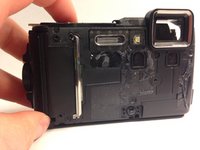
Carefully remove the back cover from the camera body.
Hi, do you have a photo of the back panel but inside, my camera it's cracked in the GPS. Pleaseeeeee
Merci Tutoriel parfait
Patrick M
The back cover is connected to the main board with two flexible flat cables (FFC). The connectors on the board have lids that lock the cables, so first lift the lids with a plastic tip, then tear the cable with no force aut of the connector.
bonjour , pour ma part le capot ne se retire pas , il semble encore retenu au niveau de la vis centrale du capot inferieur alors que j'ai retiré toute les vis !!! merci de m'eclairer
-
-
-
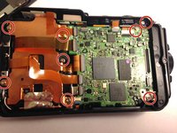
Using a Phillips #000 screwdriver, remove all 8, 4mm screws on the motherboard.
Do not remove the screw in the center. The metal bracket is only held down with four screws, so it is seven screws in total.
CAUTION:
There is a 300V / 100µF strobe capacitor under the lower edge of the PCB that might still be fully charged. The capacitor is connected to the PCB with red and black leads. Test points for the capacitor are on the upper edge of the PCB, well marked with circles and “+” and “-”. Do NOT touch or short circuit the capacitor or its test points with your fingers or any metal tool, dropped screws, ...
- Check the voltage of the capacitor with a multimeter via the test points and completely discharge it using 5W resistors (say, 10kOhm to start with, then 5k, then 2k, etc. as the voltage drops).
- Only after discharging the capacitor proceed with any further steps.
-
-
-
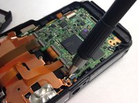
Using the nylon spudger tool, peel back the metallic plate.
-
-
-
Using your fingers, carefully disconnect the connector ribbons.
The connectors on the board have lids that lock the cables, so first lift the lids with a plastic tip, then tear the cable with no force aut of the connector. The lids are the light gray, left side, parts of the connectors as seen on the photo, here all in LOCKED position.
-
-
-
Carefully remove the black piece on the lefthand side.
From here on, I strongly suggest to proceed differently.
- Remove the metal bracket that holds the “black piece” (camera module), then take the camera module out.
- Remove one more now visible screw, located 12mm below the lower left corner of the camera window, that holds a kind of plasic finger.
- Now you can gently lift the assembly consisting of main board and battery housing and push it to the left (the open battery hatch helps in this step) to take it out. Only use plastic tools and hold the PCB only by the side if at all.
CAUTION: There is a 300V / 100µF strobe capacitor under the lower edge of the PCB that you should have discharged before.
- Now you can safely desolder the leads as described in the next steps.
-
-
-
On the remaining piece, desolder the labeled soldering points.
-
-
-
Flip the remaining piece over, careful not to rip any of the connecting wires.
-
-
-
Desolder at the prescribed sites.
-
Remove the motherboard from the camera body.
-


To reassemble your device, follow these instructions in reverse order.
To reassemble your device, follow these instructions in reverse order.
crwdns2935221:0crwdne2935221:0
crwdns2935229:03crwdne2935229:0
crwdns2915084:0crwdne2915084:0

Western Carolina University, Team 1-4, Virtue Spring 2016 crwdns2935289:0Western Carolina University, Team 1-4, Virtue Spring 2016crwdne2935289:0
WCU-VIRTUE-S16S1G4
crwdns2931471:05crwdne2931471:0
crwdns2935297:016crwdne2935297:0
crwdns2947410:01crwdne2947410:0
Thanks for this guide.
I managed to open 2 of theses and swap the sensor-unit from one to another.
Unluckily the camera remains broken since one only shows a black picture - even though the sensor is alright an the other has a broken AF from a fall, I suppose...
I am certain with some silicone grease on the orange rubber the camera would still be waterproof.