crwdns2915892:0crwdne2915892:0
The LCD screen assembly is composed of the digitizer (screen glass) and LCD. By completing all of the prerequisite guides, you will be left with your device's LCD screen assembly.
crwdns2942213:0crwdne2942213:0
crwdns2936621:0crwdne2936621:0
-
-
Power down your device.
-
Use your plastic opening tool to wedge between the seams around the sides of the device. Pry open each side, one at a time. For some a finger nail may be best. The case comes up quite high to the glass.
-
-
-
Work fingers around the seam between device and back cover. Use your plastic opening tool and fingers to separate each side until device and back cover are completely apart.
-
-
-
Insert the plastic opening tool under the side edge of the battery connector, and gently pry upward to disconnect it.
-
-
-
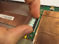
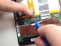
Use the flat end of a spudger or your fingernail to flip up the clear protective flap on the ribbon cable ZIF socket.
-
Using the flat end of a spudger or your fingernail, flip up the thin portion of the connector (the white part, opposite of the side where the cable inserts) to release the cable from its socket.
-
Slide the cable out of the ZIF socket.
-
-
-
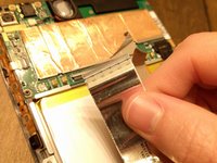
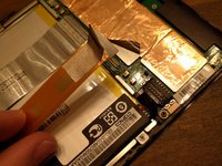
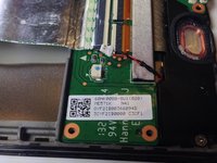
Peel protective foil cover back top of mother board to expose orange ribbon connection.
-
-
crwdns2935267:0crwdne2935267:0Tweezers$4.99
-
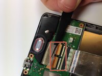
Using the tweezers, peel back the silver protective foil on top of the orange ribbon connector.
-
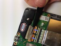
Using the plastic opening tool, pry upward under the orange ribbon connector. It will pop right out of place.
-
-
-
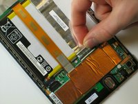
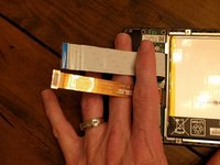
Now that the two main ribbons are disconnected, fold and hold them back with your fingers, or place the tweezers or a light object on the ribbons to keep them in place.
-
-
-
Use the #0 Phillips Screwdriver to remove the four silver 3 mm Philips #0 screws from around the battery housing.
-
-
-
-
Remove the battery from your device by applying pressure at the base of the battery and lifting it out.
-
-
-
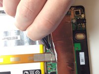
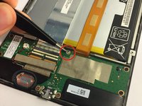
Remove the gray seal covering the top center screw on the daughterboard.
-
-
-
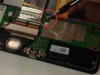
Using the Phillips #0 screwdriver, unscrew the 5 black 2 mm sized screws from around the edge of the daughterboard.
-
Use the same Phillips #0 screwdriver to remove the two silver 3 mm sized screws from either side of the micro USB.
-
-
crwdns2935267:0crwdne2935267:0Tweezers$4.99
-
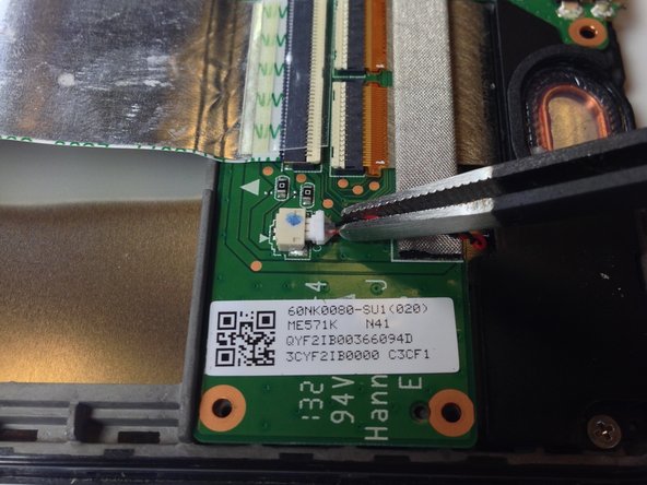
Use the tweezers to unplug the speaker connector from the daughterboard by pulling sideways.
-
-
-
Slowly peel off the EMI gasket over the ribbon cable assembly. This will expose the ribbon cable which can be removed from the connectors.
-
-
-
Use the flat end of a spudger or your fingernail to carefully flip up both retaining flaps one each of the ZIF sockets.
-
-
-
The daughterboard will now lift easily up and out of the device.
-
-
crwdns2935267:0crwdne2935267:0Tweezers$4.99
-
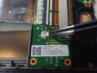
Use the tweezers to peel the seal sticker off of the center screw that is closest to the battery.
-
-
-
Using the tweezers, or carefully with your fingers, disconnect the speaker from its motherboard connection by pulling directly sideways.
-
-
-
Use the flat end of a spudger or your fingernail to carefully flip up the retaining flap on the ribbon cable ZIF socket.
-
-
-
Using the #0 Philips head screwdriver, remove the three black 2 mm screws holding the inner edge of the motherboard in place.
-
Using the #0 Philips head screwdriver, remove the five silver 3 mm screws holding the outer edge of the motherboard in place.
-
-
-
Carefully lift the motherboard up from its edge and remove it from the tablet casing.
-
-
-
Use Phillips #0 screwdriver to remove two screws from either end of the speaker.
-
-
-
Carefully lift bottom speaker from the device.
-
-
-
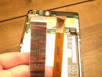
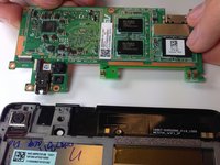
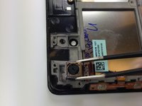
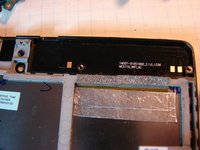
Once you have removed the back cover, battery, daughterboard, motherboard, and speakers, the LCD assembly will remain.
-
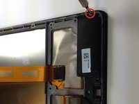
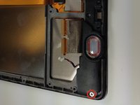
Some replacements do not include the foil switch assembly (top right in photo). If this is the case you will have to pry it gently off the old LCD assembly frame. On the new assembly watch the shape and the plastic guide pin. Alignment is important for the switches to work, once reassembled.
-


To reassemble your device, follow these instructions in reverse order.
crwdns2935221:0crwdne2935221:0
crwdns2935229:077crwdne2935229:0
crwdns2935287:0crwdne2935287:0

Cal Poly, Team 20-16, Maness Winter 2015 crwdns2935289:0Cal Poly, Team 20-16, Maness Winter 2015crwdne2935289:0
CPSU-MANESS-W15S20G16
crwdns2931471:04crwdne2931471:0
crwdns2935297:026crwdne2935297:0
crwdns2947412:016crwdne2947412:0
This provided a nice overview to replace the front panel assembly, but there were a couple items not covered or that could have been more clear (see my comments on Steps 3, 10, 14, 16, and 18).
Excellent guide. I wasn't confident I could do it but I'm writing this using the new screen now...
As far as "Flipping up the White part"....the author HAS clearly included links for this if you are unfamiliar....To me....Very well written!!...and no...I'm not the author, nor do I know him....Nice job!
Worked for me, thanks very much.
So there is no way to replace just touch screen digitizer separate of still functioning LCD screen in 2nd generation NEXUS 7 released in 2013?