crwdns2915892:0crwdne2915892:0
This repair has steps that may result in device damage, please take care and use common sense while following steps. A video is included to provide more detail into the disassembly process if you run into any issues or are confused as to how the step is described.
This disassembly guide breaks down the Nest IQ Outdoor camera to the “module” level removing all electronics from the camera. It is likely that rather than designed to be easy to repair, the module structure was chosen for ease of assembly in the factory. The LED Ring “seal” of the camera does NOT seem to be designed to be re-opened. A specialized tool may need to be developed to prevent the “prying” method used in this guide.
The modules/parts that the camera breaks down into are as follows:
- LED Light Ring
- Camera Module
- Motherboard Module
- Speaker Module (& Spring)
- Power Board
- Camera Shell/Housing
The writer of this guide and iFixit are not responsible for any damage caused to devices by the following of these steps.
crwdns2942213:0crwdne2942213:0
-
-
Carefully insert an iFixit "Jimmy" Tool (flat flexible steel blade) between the hard white plastic housing and edge of the LED light ring.
-
Pry the "Jimmy" tool slightly sideways and insert an iFixit "Metal Spudger" into the gap created. Slide it down inside the housing around half an inch.
-
Use the metal spudger to pry carefully slowly working your way in a circle around the LED Light ring to attempt to slowly work it backwards out of the housing.
I have a much easier method, just drill out the vent hole a little (I went to 3/16") and put compressed air to it, the LED ring pops right out. Make sure to have the camera face down on a soft surface.
Update to my opening suggestion, I just opened one without drilling out the vent hole. Just use a rubber tip air nozzle and move it around until centered, pops right out!
would be awesome if you can make a short video demonstration (even just to show how to do this, without opening)
Bilal -
Where can I get a link to video?
I popped out the camera assembly using Rexy624's compressed air tidbit. I used the microphone hole on the bottom using the rubber tip air nozzle. The LED and camera assembly pops out quick, so I recommend holding the Nest camera lens down on a cushion of towels.
Rexy624, pure genius, using about 100psi with the rubber tip air nozzle, give it a second or two blast and the entire sealed assembly pops out with some force.
-
-
-
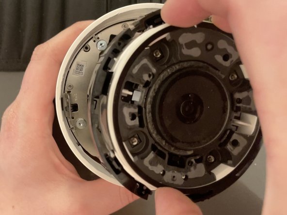
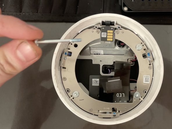
Remove each of the four screws securing the plastic ring that is holding down the camera module.
-
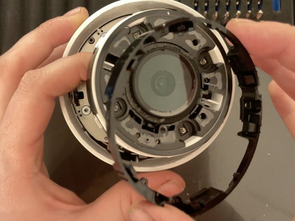
Pull the camera module upwards, and remove the black ring from around it by pulling it upward and over the camera module.
-
4 x 4.5(?)mm Torx T5 screws
Had to use a TR6 bit included in the 29 piece set that I bought from you guys to get these screws out. The T5 bit was stripping them.
-
-
-
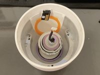
Lift the camera module up and out of the housing.
-
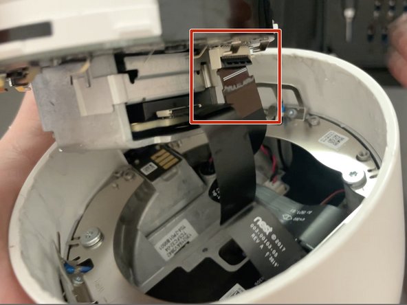
Using your fingernail pull down on the black portion of the ZIF connector to flip it into the down position.
-
Slide the LED ribbon cable out of the ZIF connector.
-
-
-
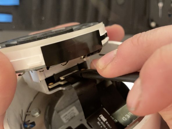
Using a flat plastic spudger push upwards on the black portion of the ZIF connector to flip it into the up position.
-
Slide the camera ribbon cable out from the connector.
-
-
-
-
Remove the 4 long screws holding the motherboard module into the camera.
-
4 x 31mm Torx T9H screw
-
-
-
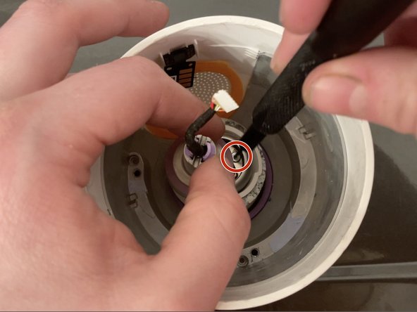
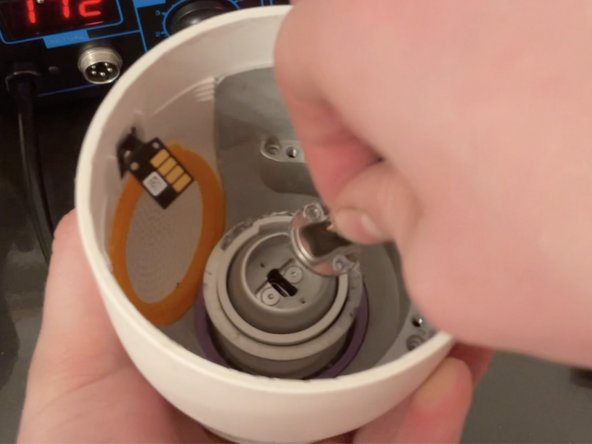
Using your fingers unplug the power connector by gently pulling upwards on the cable until the connector comes out of its socket.
-
-
crwdns2935267:0crwdne2935267:0Tweezers$4.99
-
Unplug the speaker connector next to the power connector by gripping it with metal tweezers and gently pulling directly upward.
-
-
-
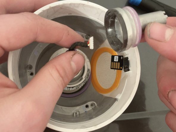
Using the flat spudger slide it under the power transfer pad to separate the glue holding the pad down.
-
Fold it up out of the way.
-
-
-
Using both hands, gently pull upwards making sure the power cable, speaker cable, and power pad route down through/around the motherboard module as you pull it upward.
-
-
-
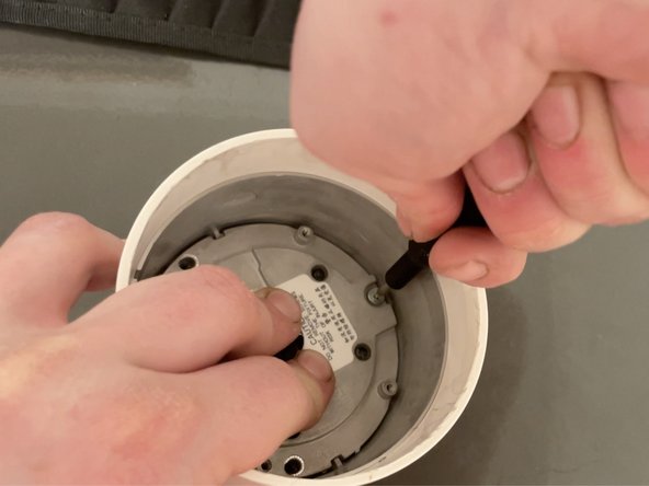
Remove the three screws holding down the speaker module.
-
3 x Torx T9 4.5(?)mm Screws
This step is difficult to reassemble. The technique I used to finally get the speaker module back together with the powerful spring was to use a wide mouth cup, which I placed the camera base in, and a thin vacuum tube to press the speaker module down. The thin vacuum tube allowed room to replace the screws.
-
-
-
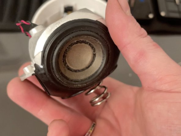
Lift the Speaker Module and Spring out of the case, threading the power cable down through the middle.
-
-
-
Bend/move the power cable to the side and remove each of the two screws holding down the Power Board.
-
2 x Torx T5 3(?)mm screws
-
-
-
Using a pair of metal tweezers push on the two pink rubber bits on the top of the power cord housing and push downwards to slide the power cord out of the housing.
-
-
-
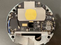
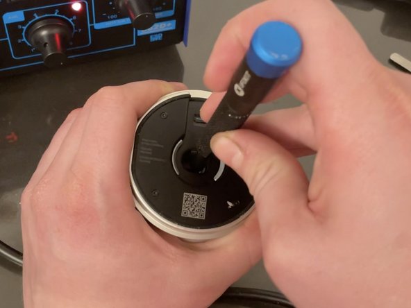
Using a heat gun melt the glue holding down the power board. The glue is placed directly under where the previous two screws were removed.
-
Using a thin tool (ideally a Male USB-C connector affixed to a rod) press out the power module. I do use the thinnest flathead screwdriver here to push on it, however this will likely damage the connector.
Focused heat works well, I used a Master Ultratorch with the hot air tip. It smells like phenolic so I think it is a phenolic rubber. It peels off easily after the heat. And that is where the water damage is, I can see a few SMD's that are green. The question is what does that board do since the camera is fed with 5V??
To remove the Power Board, I used my wife's hair dryer to heat up the assembly, and, instead of using a flathead screwdriver to push from the back, I felt safer using the flat end of two bamboo skewers. It took some force, but the power Module did come out undamaged.
-
-
-
Remove the final two screws to release the base ball joint from the inside of the housing.
-
2 x Torx T5 3(?)mm screws
-
-
-
You are now done disassembling the unit to the module level! Check out the other guides (coming soon) to see how to break down the modules further.
-


To reassemble your device, follow these instructions in reverse order.
The Camera module and LED Ring should first be connected together with the microphones and status LED properly glued to the back of the LED Ring and the connectors are attached to the camera module.
When “re-sealing” the camera the Camera LED Ring combo assembly should be attached to the ribbon cables, then pressed/snapped down into place (into the black plastic ring with clips that hold down the camera module).
crwdns2935221:0crwdne2935221:0
crwdns2935229:011crwdne2935229:0
crwdns2947412:019crwdne2947412:0
my power board has water damage. I'm trying to remove the board and direct wire it. any suggestions?
My power board also has water damage! Did you have any luck repairing yours? Cheers
If I cannot repair my power adapter, I'm considering parting mine out as there seems to be zero parts available.
I can't find the video link
Do you have the link to the video available?
I will be attempting a tear down in a few weeks; wish me luck.
Does anyone know where to buy parts etc, also my camera just turned off one day and will not turn back one if there a fix if I strip it please help me 😊
I’m having the same issue, were you able to fix yours?
eBay look for broken units and take parts from there is what I do
Joe M -
I do not have the skills or tools to do this repair. Would anyone like a non-functional camera? Happy to send it to you if you reimburse shipping costs.
link to video?
where is link to video for camera repair
I have a much easier method to open the camera, just put compressed air to the small vent hole above the speaker holes, the LED ring pops right out. Make sure to have the camera face down on a soft surface so it doesn't fly or get damaged in the process.
That worked great! Thanks for the tip!
My power board also got water damage after cutting the thick slightly soft black goo covering on the power board away I noticed a lot of water damage under. The resisters even came loose from the board. Does anyone know the resistor values on the power board?
Or was someone able to exclude this power board in any way?
What / where is the sensor for ambient light.
This sucks because of Google; where is the cord? Or is it wireless? Battery? Where is the video link? This entirely just frustrated me more than anything...
I used this ifixit guide to disassemble my Nest IQ Outdoor camera that was no longer powering on. I examined the power board and other circuits and did not see any corrosion or any signs of water intrusion. Unfortunately, I was not able to get my camera to working order. I saw some alternate power circuits available on Amazon, but I do not have the tools or knowledge to source it's power and mount it within the camera to get the camera working again.
I left a few comments on some steps that seem to have worked for me using my available tools for those seeking advice.
I seriously dislike Google for buying Nest and downgrading this awesome outdoor camera. It was sleek, secure, had great tech and hid all the wires.
From what i can tell the components that mostly corrode are capacitor, why you can direct wire the power to the red and black wired is the main board does PD power negotiation to test that the power supply is powerful enough. In theory it could be replace with a generic USB C board that has the CC1 & CC2 connection on it. If I work out the wire mapping I will post it here.
Wire mapping assuming they use the same colours
1 Red V+
2 Black - Ground
3 Yellow CC1
4 White CC2
5 Green D+ (D1+, D2+)
6 Orange D- (D1-,D2-)
Buy a USB C header PCB which gives you the CC1 & CC2 connection, the ones I got off aliexpress with a light file on the pcb corners fitted in, including screw holes.
I plan to cover in gasket sealant to weatherproof the pcb.
I do not have the skills or tools to do this repair. Would anyone like a non-functional camera? Happy to send it to you if you reimburse shipping costs.
@skyyoung this is an awesome guide. I bought a bunch of these cameras a few years ago, thinking "they're expensive but they're very capable and I'll be set for many years to come." Boy, was I wrong....they've all been failing. I called Nest/Google (I'm super confused by their relationship but that's another story) and got ZERO satisfaction. So, I've switched to RING cameras. I don't have the time or desire to fix my Outdoor IQ cameras but I sure feel bad putting them in the landfill. If you'd be interested in 3 cameras (maybe 4 if my one remaining working camera dies) and a bunch of power adapters and cords), I'd be happy to ship them do you. I'm not a regular here on iFixit so, if you're interested, please email be directly... bob.stoney@comcast.net Thanks again for the work putting this step-by-step description together!
Robert Stoney - crwdns2934203:0crwdne2934203:0