crwdns2915892:0crwdne2915892:0
If you are having issues with the Moto Z2 Force's motherboard, use this guide to replace it.
Before you begin, download the Rescue and Smart Assistant app to backup your device and diagnose whether your problem is software or hardware related.
For your safety, discharge your battery below 25% before disassembling your phone. This reduces the risk of a dangerous thermal event if the battery is accidentally damaged during the repair. If your battery is swollen, take appropriate precautions.
Warning: The screen assembly of this device is comprised of a rigid midframe and a flexible plastic display that can split apart during disassembly. Excessive heat on the display can also cause it to bubble up or warp, and this is very difficult to remedy. If you plan on reusing the screen assembly, heed all warnings carefully and do not use any heat on the display.
crwdns2942213:0crwdne2942213:0
-
-
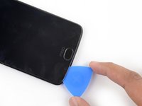
Insert the point of the SIM card eject tool into the sim card lock at the top of the phone.
-
Press down on the SIM card eject tool until the SIM card tray is slightly ejected from the device.
-
-
-
Remove the SIM card tray from the phone.
-
-
-
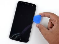
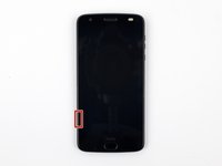
When separating the sides of the screen assembly from the device's frame, you will need to release five metal clips securing it in place.
-
Three of these clips are located on the left side of the device, and two are located on the right side.
-
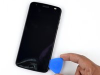
You will need to work around these clips with your opening pick in order to fully release them.
-
You can either carefully slide an opening pick around these clips, or leave a pick on one side of the clip while prying the other side with another pick.
-
-
-
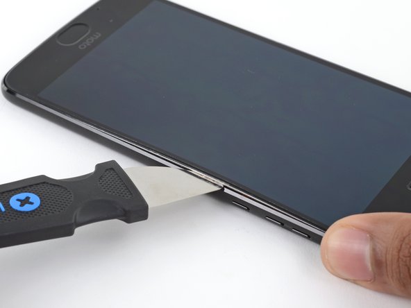
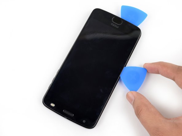
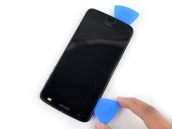
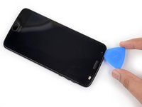
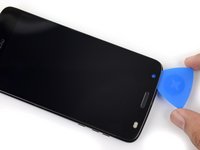
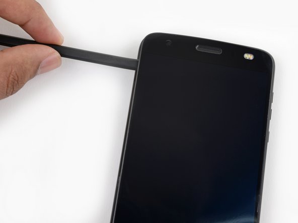
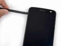
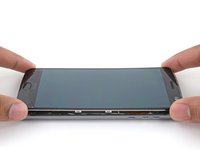
Insert a Jimmy or other metal tool between the right side of the plastic display and the metal frame, near the phone's side buttons.
-
Tilt the Jimmy downward while continuing to push it deeper into the gap to pry up the right side of the screen assembly.
-
-
-
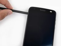
With the Jimmy still inserted, insert an opening pick under the silver midframe, on top of the Jimmy in the same location
-
Remove the Jimmy.
-
-
-
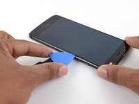
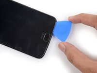
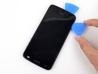
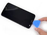
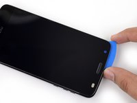
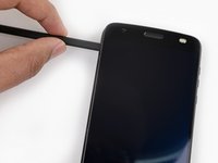
Slide your opening pick all along the right side of the device to release the clips and adhesive securing the screen assembly.
-
-
-
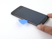
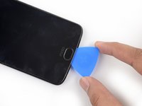
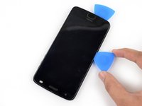
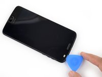
Once the screen assembly's right edge is separated, slide your pick around the bottom right corner of the device so it is underneath the bottom edge of the assembly.
-
Slide the tool all along the bottom edge of the phone to slice through the adhesive securing the screen assembly and release the plastic clips.
-
Leave your tool underneath the bottom edge of the screen assembly to prevent it from re-adhering to the frame. Continue to the next step with a new tool.
-
-
-
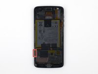
When separating the left side of the screen assembly, take care to not snag the display cable located on the left edge near the bottom of the display.
-
-
-
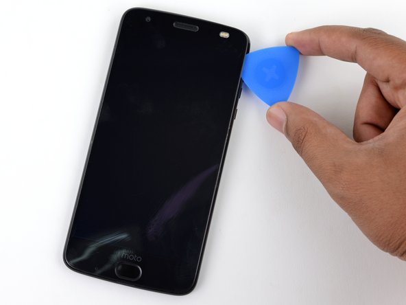
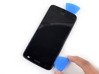
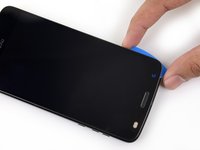
Insert another opening pick underneath the bottom edge of the screen assembly and slide it around the bottom left corner of the device so it is underneath the assembly's left edge.
-
Slide your tool all along the left edge of the phone to separate the metal clips and adhesive securing the screen assembly.
-
-
-
Slide your tool around the top edge of the screen assembly and slice all along it to slice through its adhesive.
-
-
-
-
There are two large pads of adhesive securing the screen assembly near the top edge but further past the 4 mm that have already been sliced through.
-
The front facing sensor array and cable surround the right patch of adhesive from the top and right, so prying or slicing from the top or right edge may damage the cable. The following steps will describe how to separate the adhesive from the left edge.
-
-
-
Apply a small amount of high concentration (>90%) isopropyl alcohol underneath the screen assembly's left edge, near the top of the device.
-
Allow the device to sit upright on its right edge for ~5 minutes to allow the alcohol to penetrate and weaken the adhesive.
-
-
-
Insert an opening pick as deep as possible under the top left corner of the screen assembly to slice through the left patch of adhesive.
-
-
-
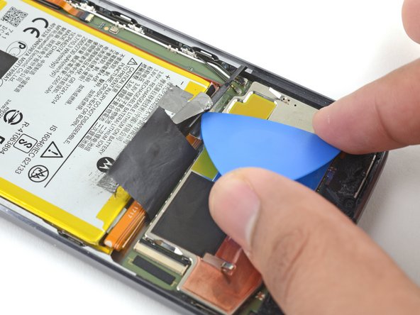
Slowly and carefully slide the flat end of a spudger under the left edge of the screen assembly. Gradually insert it deeper to pry up the top edge of the assembly and release the right patch of adhesive.
-
-
-
Lift the screen assembly from the right edge and swing it open. It is still attached to the phone chassis at the lower left edge, so do not fully remove it yet.
-
If the screen assembly remains stuck, slice the adhesive repeatedly as needed.
-
-
crwdns2935267:0crwdne2935267:0Tweezers$4.99
-
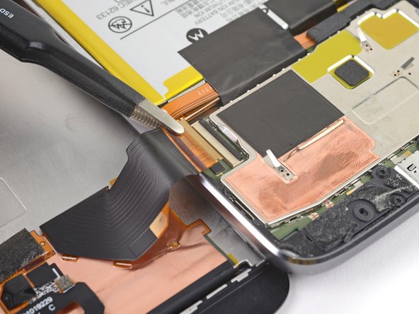
Use a pair of tweezers to remove the black piece of tape covering the battery connector.
-
-
-
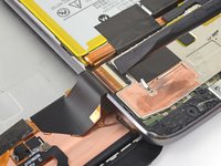
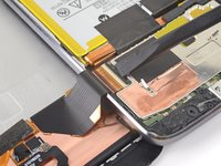
Use a spudger to pry up the locking tab on the display cable's ZIF connector.
-
Use a pair of tweezers to slide the display ribbon cable out of the connector.
-
-
-
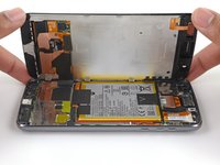
Remove the screen assembly.
-
-
crwdns2935267:0crwdne2935267:0Tesa 61395 Tape$6.99
-
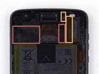
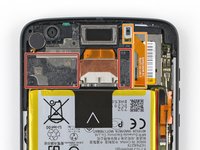
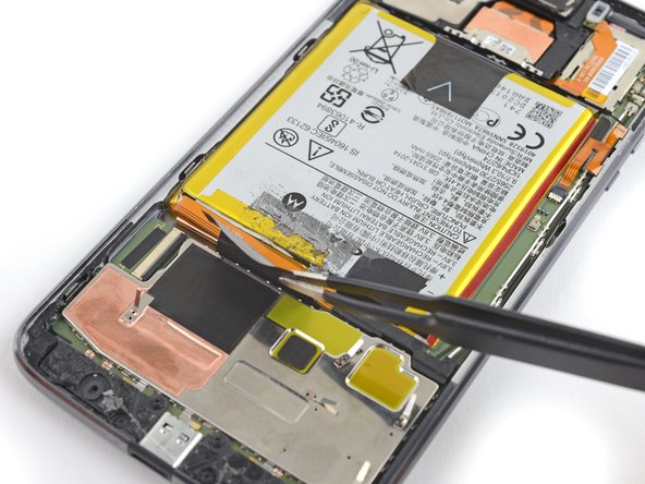
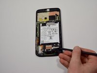
Use a pair of tweezers to remove the two black pieces of tape securing the battery.
-
-
-
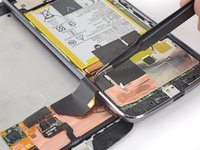
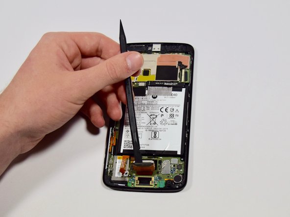
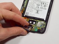
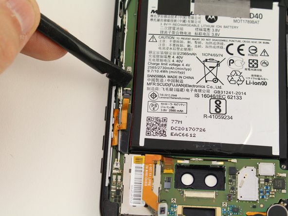
Use an opening pick to pry up the small black bracket covering the battery connector. It is secured with a small bit of adhesive.
-
Use a pair of tweezers or your fingers to remove the bracket.
-
-
-
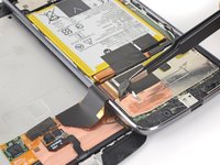
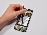
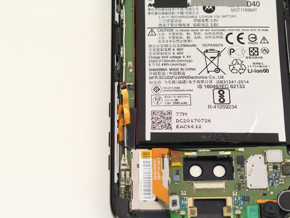
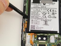
Use a spudger to pry up and disconnect the battery connector.
-
-
-
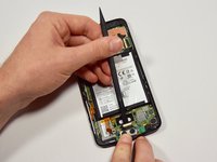
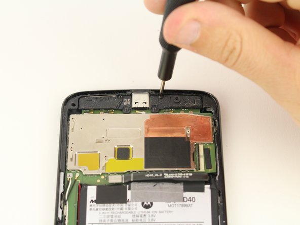
Unscrew the three 1.7mm T4 screws from the speaker.
-
-
-
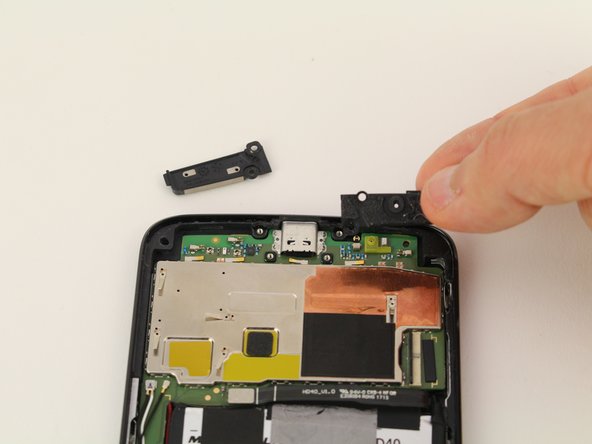
Use the nylon spudger to lift and remove the speaker from the phone chassis.
-
-
-
Insert the flat end of the nylon spudger on the side of the rear facing camera closest to the battery.
-
Pry up the camera by pushing down on the spudger until the camera pops up.
-
-
-
Insert the flat end of the nylon spudger underneath the black lock.
-
Unlock the ribbon cable by pulling up on the lock with the nylon spudger.
-
Separate the rear facing camera from the board by pulling gently towards the bottom of the phone.
-
-
-
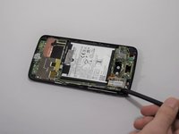
Using the spudger, lift up the bar on the ZIF connector that joins the ribbon cable to the control buttons.
-
-
-
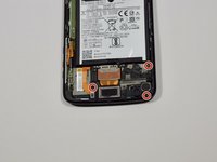
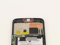
Unscrew four 1.8mm T4 screws from the speakers and remove from the motherboard.
-
-
-
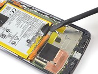
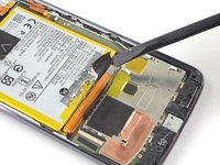
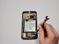
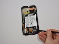
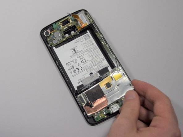
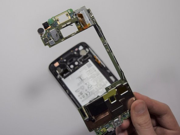
Insert the flat end of the nylon spudger underneath the edge of the phone near the camera.
-
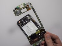
Gently pry the motherboard from the phone until it is raised enough to put a finger between it and the phone.
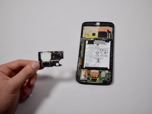
-
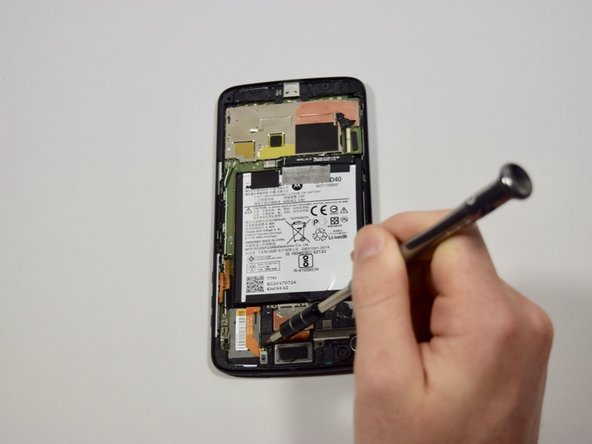
With your fingers, gently pry the rest of the motherboard up from the phone.
-


To reassemble your device, follow these instructions in reverse order.
crwdns2935221:0crwdne2935221:0
crwdns2935229:05crwdne2935229:0

crwdns2935287:0crwdne2935287:0

Cal Poly, Team S2-G1, Livingston Winter 2018 crwdns2935289:0Cal Poly, Team S2-G1, Livingston Winter 2018crwdne2935289:0
CPSU-LIVINGSTON-W18S2G1
crwdns2931471:04crwdne2931471:0
crwdns2935297:028crwdne2935297:0
crwdns2947412:04crwdne2947412:0
My lcd came apart the entire assembly didn't come up as the instructions showed it would and it tore the ribbon connector.
This phone is not a good first DIY for anyone. I’ve been repairing phones since years and i separated the AMOLED panel from it’s frame too. Lucky me i was gently, used a lot of heat and flooded it with IPA so i could still re use this panel, but i realized it can be a pain in the ass for someone less expert than me.
Rafael B -
Rafael, I also detached (partially) the AMOLED panel from the frame and now my display don’t light anymore. I know this not other part’s fault, because the phone vibers when I press the power button and also when I touch the fingerprint sensor. There is no visual damage neither in display/frame or the cables. A partial detaching is enough to make the screen dont power up anymore? Or is something else causing this problem?
For &&^&* sake, you tell me to be careful not to remove the screen assembly AFTER the step where it's pried apart!? Is there nothing I can do??