crwdns2915892:0crwdne2915892:0
If your rear facing camera is damaged and not letting you take photos or videos, this guide will show you how to remove and replace it so your Motorola Moto G5 Plus is working at peak condition.
crwdns2942213:0crwdne2942213:0
-
-
Use a SIM eject bit, SIM eject tool, or paper clip to remove the SIM card from your phone.
-
-
-
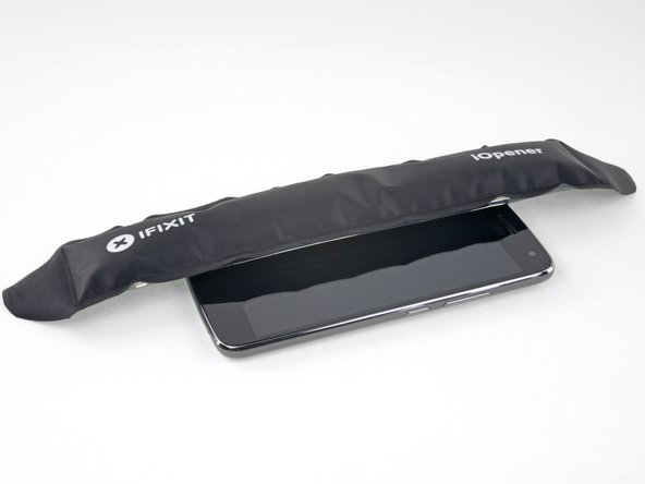
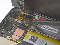
Prepare an iOpener and heat the front of the phone along its left edge for about two minutes, or until it's slightly too hot to touch. This will help soften the adhesive securing the display.
-
-
-
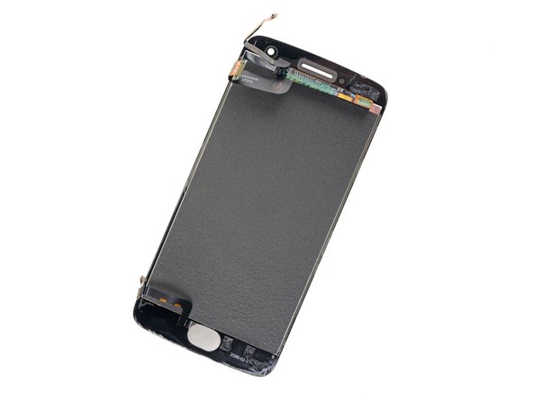
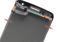
Refer to the second and third images and familiarize yourself with the width of the adhesive around edges of the display.
-
-
-
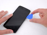
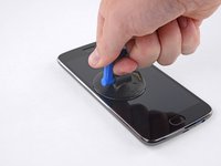
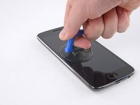
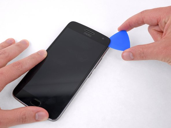
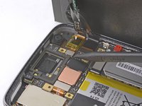
Apply a suction cup to the display, near the middle of the left edge.
-
Pull the suction cup with firm, constant pressure to create a slight gap between the display panel and the rear case.
-
If the display doesn't separate even with significant force, apply more heat to further soften the adhesive and try again. The adhesive cools quickly, so you may need to heat it repeatedly.
-
-
-
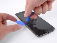
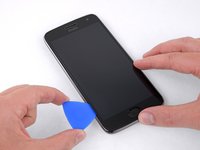
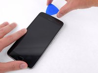
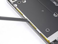
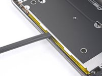
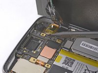
Slide the tool along the left edge of the phone, cutting through the adhesive securing the display.
-
-
-
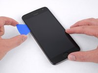
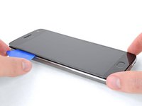
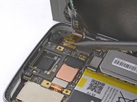
Slide the opening pick down and cut the adhesive around the bottom of the display.
-
-
-
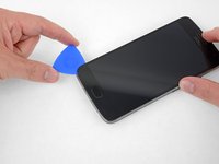
Continue cutting through the adhesive on the top and right sides of the phone.
-
-
-
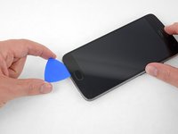
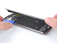
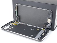
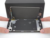
Once all the adhesive is cut, carefully lift open the display from the left edge.
-
Prop the display unit at a 90 degree angle against a box to prevent the display and fingerprint cables from bending or tearing.
-
-
-
Remove the yellow sticker covering two of the black Phillips screws below the earpiece.
-
-
-
Remove the following Phillips screws from the midframe:
-
Sixteen 3.8 mm black screws
-
Three 2.4 mm silver screws
-
-
-
-
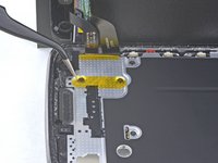
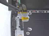
Insert the flat end of a spudger between the midframe and the left edge of the phone and carefully pry to release the two clips holding the midframe in place.
-
-
-
Lift the midframe up and away from the phone.
-
-
-
Use the point of a spudger to disconnect the larger of the two display cable connectors.
-
-
-
Disconnect the smaller display cable connector.
-
Gently continue lifting the cable to break the adhesive seal and pull the cable away from the motherboard.
-
-
-
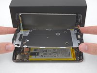
At the opposite end of the phone, disconnect the fingerprint sensor cable.
-
-
-
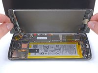
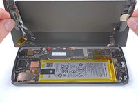
Remove the display assembly from the phone.
-
-
-
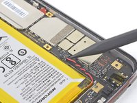
Remove the yellow tape covering the battery connector.
-
-
-
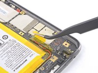
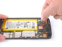
Use the point of a spudger to disconnect the battery by prying its connector straight up from the motherboard.
-
-
-
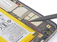
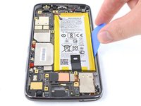
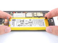
Peel back the black pull tab from the top of the battery and pull straight up with firm, steady pressure to break the adhesive holding the battery in place.
-
-
-
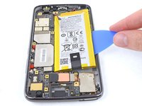
If your pull tab breaks or the adhesive is too strong to break, use an opening pick to gently pry the battery out of the case.
-
-
crwdns2935267:0crwdne2935267:0Tesa 61395 Tape$5.99
-
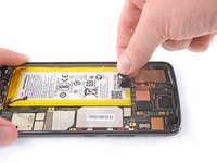
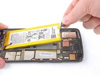
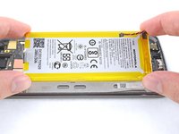
Once the battery is loose, remove it from the phone.
-
Remove any remaining adhesive from the phone, and clean the entire area under the battery with isopropyl alcohol.
-
Apply a few new strips of pre-cut adhesive or Tesa tape.
-
Press the new battery firmly into place for 5-10 seconds.
-
-
-
Using the Philips 000 Screwdriver, unscrew the 3.1 mm screw.
-
-
-
Using the plastic opening tool, unplug the oscillating vibration motor.
-
-
-
Unplug the flat-top connector with the plastic opening tool.
-
-
-
Using the plastic opening tool, pry open the two tabs that hold the motherboard to the phone frame.
-
-
-
Remove the motherboard from the phone by prying it up with the plastic opening tool.
-
-
-
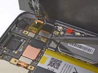
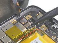
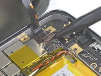
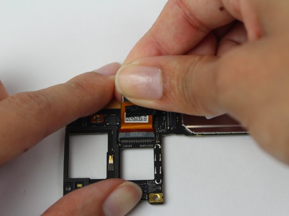
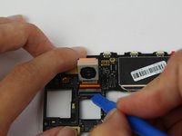
Gently pry the 12-megapixel G5 Plus rear-facing camera up using the plastic opening tool, exposing the ZIF connector.
-
-
-
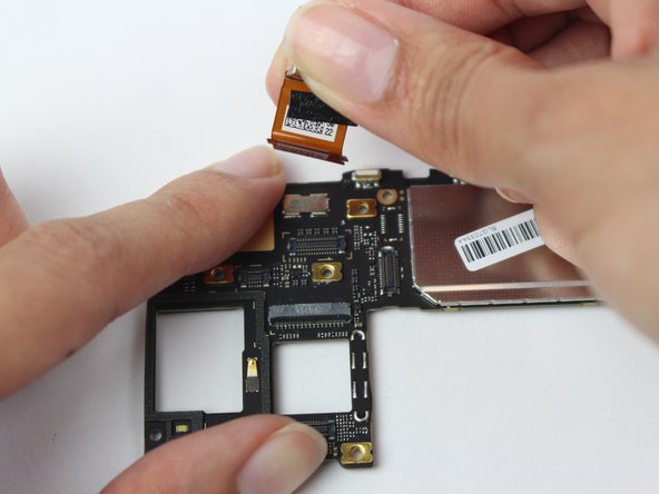
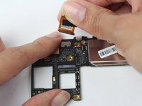
Release the ZIF connector and remove the camera from the board.
-


To reassemble your device, follow these instructions in reverse order.
To reassemble your device, follow these instructions in reverse order.
crwdns2935221:0crwdne2935221:0
crwdns2935229:05crwdne2935229:0

crwdns2915084:0crwdne2915084:0

USF Tampa, Team S1-G6, Leahy Fall 2017 crwdns2935289:0USF Tampa, Team S1-G6, Leahy Fall 2017crwdne2935289:0
USFT-LEAHY-F17S1G6
crwdns2931471:05crwdne2931471:0
crwdns2935297:021crwdne2935297:0