crwdns2915892:0crwdne2915892:0
The motherboard of the Droid RAZR houses a number of critical components, including the SD and SIM card readers, vibrator motor, lower microphone, and microSD and micro HDMI ports.
crwdns2942213:0crwdne2942213:0
-
-
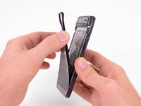
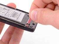
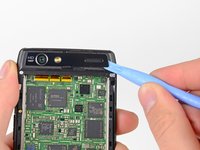
Insert a plastic opening tool between the back cover and rear case at the lower left edge of the back cover.
-
Pry the back cover up with the plastic opening tool to free the plastic clips.
-
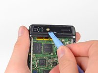
Continue prying along the left edge of the back cover towards the top of the phone.
-
-
-
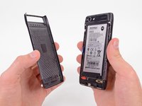
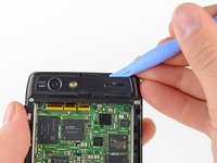
Work the plastic opening tool across the top of the back case to free the plastic clips.
-
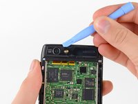
Continue prying down the right side of the back cover to free the remaining clips.
-
-
-
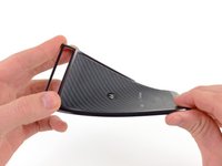
Pull the back cover away from the phone to remove it.
-
-
-
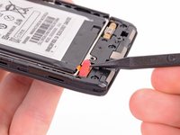
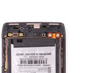
Use the tip of a spudger to lift up the red silicone cover over the battery terminal screws and remove it.
I did this repair on a Droid Razr model xt912. My version has a plastic shield over the battery connectors; the shield is part of the rear case, so I had to do steps 6-9 before I could do steps 4 and 5.
Thank you so much for this comment - saved me a lot of confusion.
Also noted that not all screws were the same as noted. I was just careful and made sure they bit fit before torking.
What are steps 6-9? This article store at step 5. The terminals on my phone are covered too and it's not obvious how it is removed.
Excellent guide, but it forgot to include that you need to get double sided adhesive to replace the old adhesive. Maybe its implied? Anyways I got mine from here: http://www.repairsuniverse.com/3m-double...
Step 1 should be to remove the case screws. No way your removal tool will get the back off with the screws still on.
Mine was on too tight to pry off. Even with small screwdrivers I was unable to get the case opened up all they way around without bending the edge metal out of shape (which is the reason for a plastic tool).
If you have the wireless charging coil installed, you can forget the adhesive back.
-
-
-
Remove the two 3.3 mm T5 Torx battery terminal screws.
-
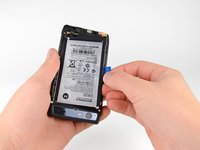
Grab the blue battery removal tab and lift the battery out to remove it.
Very helpful, but I needed to remove the frame around the battery before I could actually get the battery out. No big deal, just a few more screws. Thanks.
That’s actually pretty vital to the whole removal process.
Anyone know somewhere to purchase these “3.3 mm” terminal screws if ever lost?
-
-
-
Use a heat gun or hair dryer to soften the adhesive underneath the camera cover.
-
Gently pry up the bottom edge of the camera cover with a plastic opening tool.
-
Carefully slide the plastic opening tool across the bottom edge to free it from the adhesive.
-
Continue to use the heat gun as needed to soften the adhesive as you remove the camera cover.
Is it really necessary to remove the camera cover to replace the display assembly??? Reviewing the rest of the steps to the display, I could see no reson to remove the camera cover. Of course I've not begun my own disassembly yet, but when I do I'll see if the camera cover can be left in place and let you know how it goes.
Yes. Check the step 8. The camera cover hide one T3 torx screw.
-
-
-
Insert the plastic opening tool underneath the top edge of the camera cover.
-
Gently pry the camera cover up as you slide the plastic opening tool across the top edge to free it from the adhesive.
-
Remove the camera cover.
-
-
-
-
Remove the six screws securing the rear case to the rest of the phone:
-
three 6.7 mm silver T3 Torx screws at the top,
-
four 4.0 mm gold T3 Torx screws in the middle,
-
and three 4.5 mm black T5 Torx screws at the bottom.
Some phone models with have T3 torx screws (orange circles)
MIND YOU !
This is a mistake or the production process has been altered.
Infact, all but 3 (of all screws described as T3) are infact T4 !
You can imagine my face when I took the phone apart today and the T3 driver head didn't fit -.-
I am unable to remove the top screw next to the camera, it seems to be completely ground, I have a replacement screen (without front plastic casing) and cannot proceed without getting the screw off.. need help!
is cutting through the plastic casing an option??
I am also having trouble with the top middle screw. After working to turn the screw it became stripped. Very gently and very slowly I drilled away the head of the screw, and completed the disassembly. But the rest of the body of the screw is still in the post, and it seems too risky to try to drill anymore. Any advice on how to remove the rest of the screw or resecure this section when I put everything back together?
-
-
-
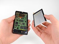
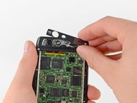
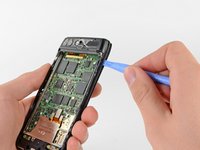
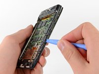
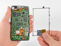
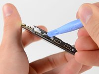
Insert a plastic opening tool between the rear case and the motherboard assembly.
-
Work your way down the side of the phone and gently pry the rear case up.
-
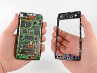
Separate the rear case from the motherboard assembly.
-
-
-
Remove the three 2.5 mm T3 Torx screws securing the metal chassis to the motherboard.
-
Remove the metal chassis from the motherboard assembly.
-
-
-
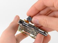
Use the flat end of a spudger to remove the two red silicone microphone covers at the top and bottom of the motherboard.
-
-
-
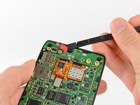
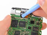
Use the tip of a spudger to gently bend the clips out of shape and remove the shield.
-
-
-
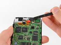
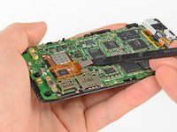
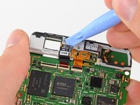
Use the flat end of a spudger to pry the three display cable connectors off their sockets on the motherboard.
-
-
-
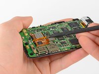
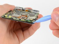
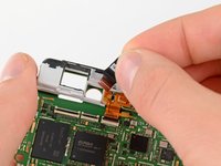
Release the securing clips with a plastic opening tool.
-
-
-
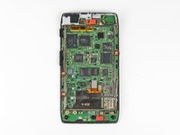
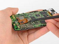
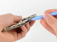
Use a heat gun or hair dryer to soften the adhesive strip around the perimeter of the motherboard.
-
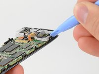
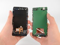
Pry the edges of the motherboard up from the display assembly with a plastic opening tool.
-
Remove the motherboard assembly.
-
-
-
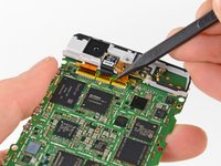
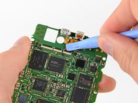
Lift up the anti-static tape covering the camera and earpiece ZIF connectors with the tip of a spudger.
-
Peel back the tape and remove it.
-
-
-
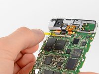
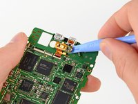
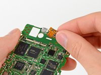
Use a plastic opening tool or your fingernail to lift up the tab on the rear-facing camera ribbon cable ZIF connector.
-
Push the rear-facing camera through its hole in the grey antenna and remove it.
-
-
-
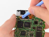
Use a plastic opening tool or your fingernail to lift up the tab on the front-facing camera ribbon cable ZIF connector.
-
Lift the front-facing camera out of the antenna with the plastic opening tool and remove it.
-
-
-
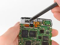
Flip up the tab on the earpiece speaker ZIF connector with your finger or a plastic opening tool.
-
Remove the earpiece speaker from the motherboard.
-
-
-
The motherboard remains.
-


To reassemble your device, follow these instructions in reverse order.
To reassemble your device, follow these instructions in reverse order.
crwdns2935221:0crwdne2935221:0
crwdns2935229:011crwdne2935229:0

crwdns2947410:01crwdne2947410:0
Does anybody do charging port repairs on a droid razor ?
I don't have the tools and would rather donate so somebody who has them.....