crwdns2915892:0crwdne2915892:0
Replace your broken LCD to bring new life to your dying Droid.
crwdns2942213:0crwdne2942213:0
-
-
Slide the battery cover downwards while applying pressure to the center of the battery cover with your thumb.
-
Lift and remove the battery cover out from the phone.
-
-
-
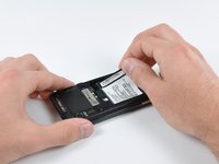
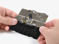
Grasp the upper left corner of the battery and lift it out of its housing.
-
-
-
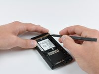
Use a spudger to lift and remove the black plastic screw cover at the top of the phone near the camera.
-
-
-
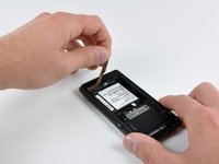
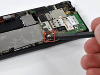
Using the tip of a spudger, peel up one corner of the gold ribbon beneath the battery compartment.
-
Peel the ribbon up off the phone.
-
-
-
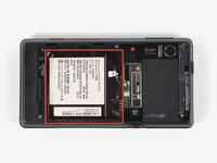
Carefully peel the device information label that covers the motherboard EMI shields.
-
-
-
Insert the flat end of a spudger and pry the plastic camera cover up off the phone.
-
-
-
Remove the seven 5.5 mm T5 Torx screws securing the rear case to the inner case.
-
-
-
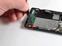
Insert the flat end of a spudger and pry downwards to release the plastic tab holding the rear case to the motherboard screw.
-
-
-
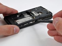
Gently insert a spudger between the rear case and front case at the top of the phone, near the audio jack.
-
Carefully pry the top edge of the rear case up from the rest of the phone.
-
-
-
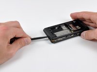
With the spudger still inserted between the rear case and front case, slide the spudger along the right edge of the device, moving toward the bottom, prying as you go.
-
Continue prying along the bottom edge of the device from right to left, freeing it from the front panel.
-
-
-
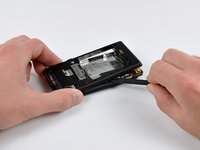
Continue prying the rear case from the front case along the left side, moving from bottom to top.
-
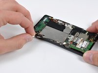
Lift the rear case up out of the phone.
-
-
-
Carefully lift and remove the speaker assembly up out of the phone.
-
-
-
-
Use a spudger to pry the antenna cable connectors from their respective sockets on the motherboard and the speaker/antenna board.
-
De-route the antenna cable by pulling it out of the metal clips along the side of the front case.
-
-
-
Peel the black tape covering the side button and display ribbon connectors on the motherboard.
-
-
-
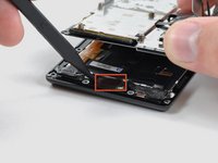
Disconnect the power button/volume button connector from its socket on the motherboard using the flat end of a spudger.
-
-
-
Disconnect the display ribbon connector from its socket on the motherboard using the flat end of a spudger.
-
-
-
Remove three 3.8 mm T5 Torx screws securing the motherboard to the front case.
-
-
-
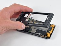
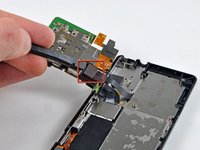
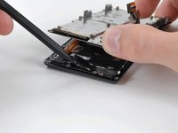
Disconnect the keypad connector by prying it straight up off its socket on the motherboard.
-
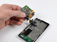
Remove the motherboard from the phone.
-
-
-
Disconnect the camera button/vibrator connector by prying it straight up off its socket on the speaker board with a spudger.
-
-
-
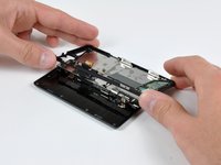
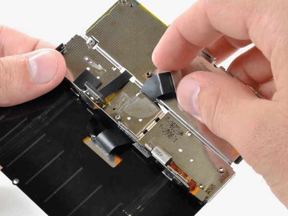
Lift up the edge of the black plastic rim that includes the speaker board from the side closest to the keypad.
-
Continue lifting the side of the rim until it is almost vertical, and wiggle it free from the back of the LCD assembly.
-
-
-
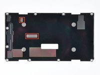
Remove the EMI shield by releasing the clips shown with the tip of a spudger.
-
-
-
Remove the five 2.5 mm Phillips screws.
-
It's either a 2.5 MM Phillips or a T4 Torx. Motorola changed it on later models of the A956.
-
-
-
Remove the single 2.5 mm Phillips screw.
-
-
-
Remove the four 2.5 mm Phillips screws.
-
-
-
Peel the display ribbon up from the keypad's metal backing.
-
-
-
Insert a spudger between the back and front case of the display assembly, and peel the two ribbon cables off the two adhesive pads along the back case of the display assembly.
-
-
-
Use the flat end of a spudger to lift the board that contains the ambient light sensor and display data cable connector out of the screen housing.
-
-
-
Use the tip of a spudger to lift the speaker out of the screen housing.
-
-
-
Peel off the black tape to reveal the front panel connector.
-
-
-
Use the flat end of a spudger or your fingernail to flip up the retaining flap on the front panel ribbon cable ZIF socket.
-
Disconnect the front panel ribbon cable.
-
-
-
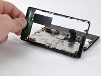
Flip the phone over and remove the front panel.
-
-
-
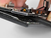
While feeding the display ribbon cable through the slot in the metal keypad backing, slowly continue to slide the phone open past its normal allowed point.
-
Continue feeding the display ribbon cable through and sliding the phone until the LCD assembly is separated from the keypad.
-
-
-
Lift the back cover off the display assembly, feeding the ribbon cable through the slit as you go.
-
-
-
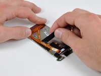
Peel away the black tape to reveal the display data cable connector.
-
-
-
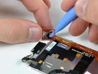
Use an iPod opening tool or fingernail to flip up the black lever on the ZIF connector.
-
Pull the orange display data cable from the ZIF connector.
-
-
-
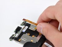
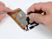
Peel the display ribbon cable from the back of the LCD. The ribbon cable is attached with adhesive, so work slowly to avoid damaging it.
-
Remove the display ribbon from the back of the LCD.
-


To reassemble your device, follow these instructions in reverse order.
To reassemble your device, follow these instructions in reverse order.
crwdns2935221:0crwdne2935221:0
crwdns2935229:015crwdne2935229:0
