crwdns2933423:0crwdne2933423:0

Motorola Defy XT Logic Board Replacement

crwdns2942213:0crwdne2942213:0

  1. Motorola Defy XT Logic Board Replacement, Logic Board: crwdns2935265:01crwdnd2935265:01crwdnd2935265:01crwdne2935265:0
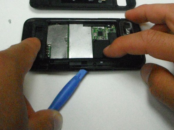
    • Wedge the opening tool in-between the back cover and the body of the phone in the opening denoted by the arrow.

  2. Motorola Defy XT Logic Board Replacement: crwdns2935265:02crwdnd2935265:01crwdnd2935265:01crwdne2935265:0
    • Once wedged in the opening, slide the opening tool around the side of the phone and remove the back cover, setting it aside.

  3. Motorola Defy XT Logic Board Replacement: crwdns2935265:03crwdnd2935265:01crwdnd2935265:01crwdne2935265:0
    • Insert the opening tool between the battery and the battery holder and wedge the battery out.

  4. Motorola Defy XT Logic Board Replacement: crwdns2935265:04crwdnd2935265:01crwdnd2935265:01crwdne2935265:0
    • Open the plastic cover with your finger to expose the SD card.

    • Use the opening tool to grab the edge of the SD card and pull it straight out.

  5. Motorola Defy XT Logic Board Replacement: crwdns2935265:05crwdnd2935265:01crwdnd2935265:01crwdne2935265:0
    • Remove the six 6mm T4 screws with the T4 torque driver.

  6. Motorola Defy XT Logic Board Replacement: crwdns2935265:06crwdnd2935265:01crwdnd2935265:01crwdne2935265:0
    • Pop out the volume button with the plastic opening tool.

  7. Motorola Defy XT Logic Board Replacement: crwdns2935265:07crwdnd2935265:01crwdnd2935265:02crwdne2935265:0 Motorola Defy XT Logic Board Replacement: crwdns2935265:07crwdnd2935265:02crwdnd2935265:02crwdne2935265:0
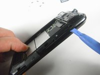
    • Wedge the plastic opening tool in-between the plastic layer and the front cover.

    • Do not completely separate the two pieces to avoid damaging the ribbon cable inside.

  8. Motorola Defy XT Logic Board Replacement: crwdns2935265:08crwdnd2935265:01crwdnd2935265:01crwdne2935265:0
    • Carefully separate the bottom piece from the top plastic piece.

    • Disconnect the ribbon cable connecting the display to the logic board by firmly pulling the cable straight outward.

    • The screen can now be removed.

  9. Motorola Defy XT Logic Board Replacement: crwdns2935265:09crwdnd2935265:01crwdnd2935265:01crwdne2935265:0
    • Separate the logic board and the display cover from the back cover and orient the logic board so the camera faces toward you.

    • Disconnect the back cover by wedging the plastic opening tool in between the motherboard and the connector and prying outward.

  10. Motorola Defy XT Logic Board Replacement: crwdns2935265:010crwdnd2935265:01crwdnd2935265:01crwdne2935265:0
    • Flip the logic board and display cover over so the camera faces away from you.

    • Bend the two halves of the device away from you to pry the final ribbon connector off the logic board.

    • The ribbon connector is bonded to the logic board with adhesive, simply pull it to break the glue bond.

crwdns2915888:0crwdne2915888:0

To reassemble your device, follow these instructions in reverse order.

crwdns2935229:02crwdne2935229:0

No Name

crwdns2935283:004/21/13crwdne2935283:0

25 crwdns2915208:0crwdne2915208:0

crwdns2935295:0crwdne2935295:0

crwdns2944067:00crwdne2944067:0

crwdns2917038:0crwdne2917038:0

crwdns2936625:0crwdne2936625:0:

crwdns2936751:024crwdne2936751:0 0

crwdns2936753:07crwdne2936753:0 0

crwdns2936753:030crwdne2936753:0 11

crwdns2942667:0crwdne2942667:0 1,316