crwdns2933423:0crwdne2933423:0

Motor and Crankcase Separation

crwdns2862623:0crwdne2862623:0
crwdns2942641:0crwdne2942641:0

crwdns2942213:0crwdne2942213:0

  1. Motor and Crankcase Separation, Disconnect the spark plug wire: crwdns2935265:01crwdnd2935265:01crwdnd2935265:02crwdne2935265:0 Motor and Crankcase Separation, Disconnect the spark plug wire: crwdns2935265:01crwdnd2935265:02crwdnd2935265:02crwdne2935265:0
    • Ensure the device is powered down and cool to the touch before starting your repair.

    • Firmly grip the base of the spark plug wire's connector and pull it away from the spark plug to disconnect it.

  2. Motor and Crankcase Separation, Loosen the sight gauge: crwdns2935265:02crwdnd2935265:01crwdnd2935265:01crwdne2935265:0
    • Use a 1-1/16 inch socket to break loose the oil sight gauge near the bottom of the device.

    • Do not fully remove the oil sight gauge yet with the device in this upright position.

    • The oil sight gauge doubles as the oil drain and fill plug.

  3. Motor and Crankcase Separation, Prepare a drain pan: crwdns2935265:03crwdnd2935265:01crwdnd2935265:01crwdne2935265:0
    • Lay the device down horizontally with the oil sight gauge facing down.

    • Position a shallow oil drain pan underneath the sight gauge.

  4. Motor and Crankcase Separation, Drain the oil: crwdns2935265:04crwdnd2935265:01crwdnd2935265:01crwdne2935265:0
    • Remove the oil sight gauge.

    • Let the oil drain until drips are infrequent.

    • Replace and retighten the oil sight gauge.

    • This model requires 0.7 liters of SAE 10W-40 oil.

  5. Motor and Crankcase Separation, Support the device: crwdns2935265:05crwdnd2935265:01crwdnd2935265:02crwdne2935265:0 Motor and Crankcase Separation, Support the device: crwdns2935265:05crwdnd2935265:02crwdnd2935265:02crwdne2935265:0
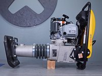
    • Flip the device onto the work surface such that the motor and handles face up.

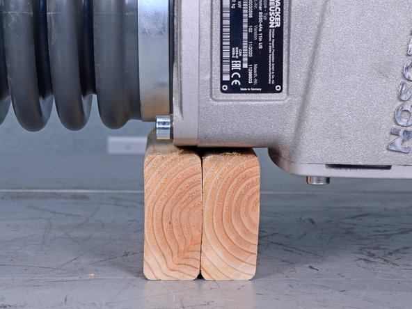
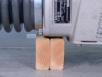
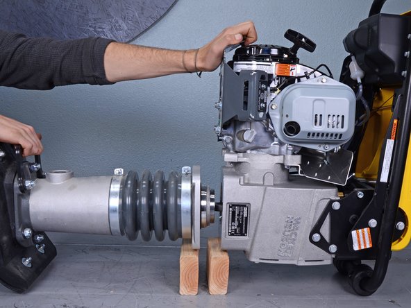
    • Place two separate blocks of wood underneath the seam between the leg assembly and crankcase.

    • Once the two halves separate, each side will need to be supported.

  6. Motor and Crankcase Separation, Remove the leg assembly bolts: crwdns2935265:06crwdnd2935265:01crwdnd2935265:02crwdne2935265:0 Motor and Crankcase Separation, Remove the leg assembly bolts: crwdns2935265:06crwdnd2935265:02crwdnd2935265:02crwdne2935265:0
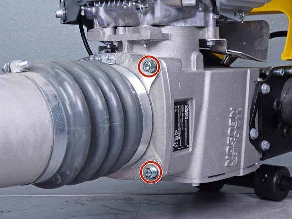
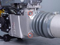
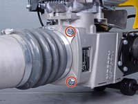
    • Use an 8 mm hex key socket to remove the four bolts securing the leg's guiding cylinder to the crankcase.

    • You may need to use an impact driver or breaker bar to break these bolts loose.

    • During reassembly, ensure each bolt has its accompanying lock washer.

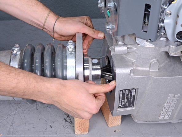
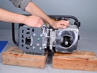
  7. Motor and Crankcase Separation, Begin to separate the halves: crwdns2935265:07crwdnd2935265:01crwdnd2935265:02crwdne2935265:0 Motor and Crankcase Separation, Begin to separate the halves: crwdns2935265:07crwdnd2935265:02crwdnd2935265:02crwdne2935265:0
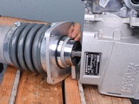
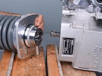
    • Pull the leg assembly away from the rest of the device.

    • Ensure each half stays adequately supported.

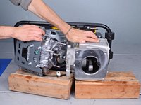
  8. Motor and Crankcase Separation, Reveal the pin: crwdns2935265:08crwdnd2935265:01crwdnd2935265:03crwdne2935265:0 Motor and Crankcase Separation, Reveal the pin: crwdns2935265:08crwdnd2935265:02crwdnd2935265:03crwdne2935265:0 Motor and Crankcase Separation, Reveal the pin: crwdns2935265:08crwdnd2935265:03crwdnd2935265:03crwdne2935265:0
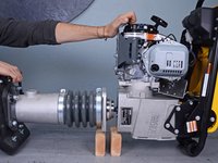
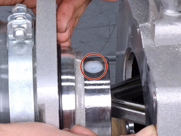
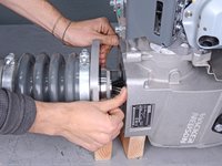
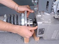
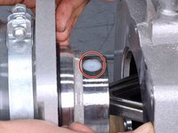
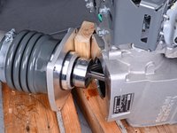
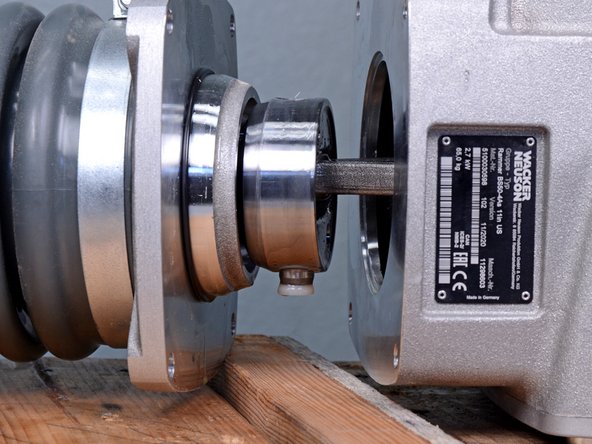
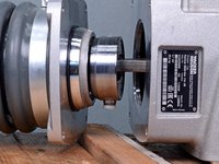
    • Continue to separate the two halves by compressing the bellows until the nylon plug covering the piston pin is visible.

  9. Motor and Crankcase Separation, Procedure tip: crwdns2935265:09crwdnd2935265:01crwdnd2935265:02crwdne2935265:0 Motor and Crankcase Separation, Procedure tip: crwdns2935265:09crwdnd2935265:02crwdnd2935265:02crwdne2935265:0
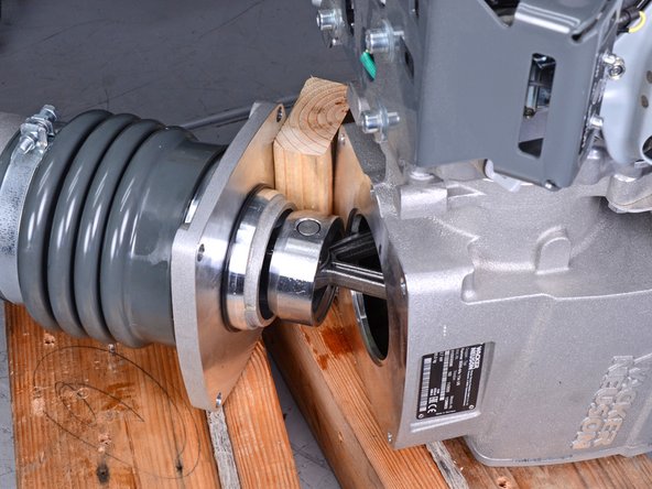
    • Tip: To compress the bellows, insert a block of wood between the two halves and pivot the leg assembly off of the crankcase to compress the guide cylinder, revealing the pin.

  10. Motor and Crankcase Separation, Remove the pin: crwdns2935265:010crwdnd2935265:01crwdnd2935265:03crwdne2935265:0 Motor and Crankcase Separation, Remove the pin: crwdns2935265:010crwdnd2935265:02crwdnd2935265:03crwdne2935265:0 Motor and Crankcase Separation, Remove the pin: crwdns2935265:010crwdnd2935265:03crwdnd2935265:03crwdne2935265:0
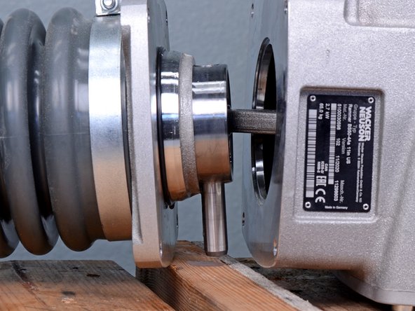
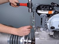
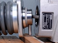
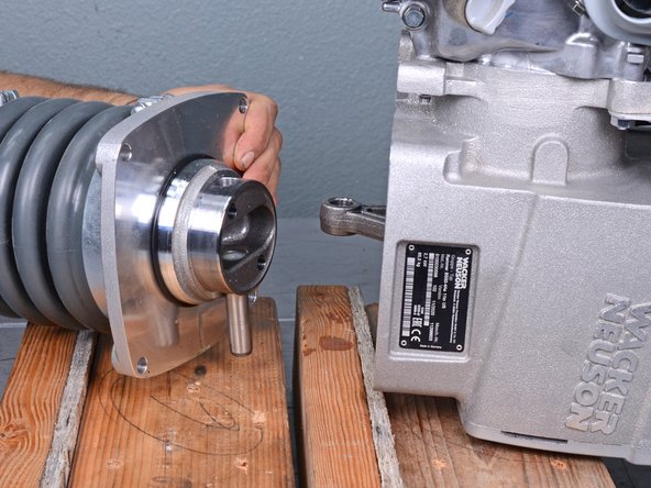
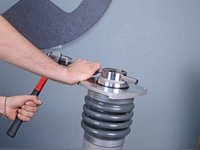
    • Use an appropriately-sized punch and a ball-peen hammer to tap the pin out of its hole on the guide piston until it is no longer securing the connecting rod.

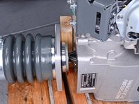
    • Once the piston and connecting rod are separated, the two halves become completely disconnected and will need to be adequately supported.

    • During reassembly, ensure that both nylon plugs are reinstalled and are flush with the surface of the guide piston.

  11. Motor and Crankcase Separation, Remove the leg assembly: crwdns2935265:011crwdnd2935265:01crwdnd2935265:02crwdne2935265:0 Motor and Crankcase Separation, Remove the leg assembly: crwdns2935265:011crwdnd2935265:02crwdnd2935265:02crwdne2935265:0
    • Remove the leg assembly from the crankcase.

  12. Motor and Crankcase Separation, Completely remove the pin: crwdns2935265:012crwdnd2935265:01crwdnd2935265:02crwdne2935265:0 Motor and Crankcase Separation, Completely remove the pin: crwdns2935265:012crwdnd2935265:02crwdnd2935265:02crwdne2935265:0
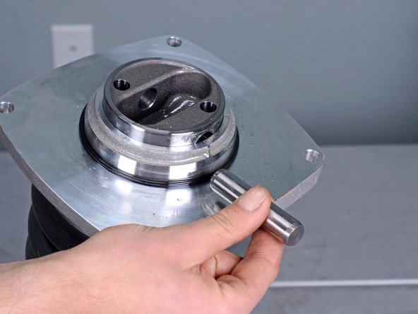
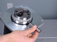
    • Use a punch and hammer to tap the pin out of the guide piston.

    • Once the pin is removed, the guide cylinder may spring up due to the compression of the bellows.

    • During reassembly, the bellows will need to be compressed to uncover the pin hole on the guide piston.

  13. Motor and Crankcase Separation, Support the device in an upright position: crwdns2935265:013crwdnd2935265:01crwdnd2935265:01crwdne2935265:0
    • Use wood blocks to support the device on the work surface, motor facing up.

  14. Motor and Crankcase Separation, Remove the engine guard: crwdns2935265:014crwdnd2935265:01crwdnd2935265:01crwdne2935265:0
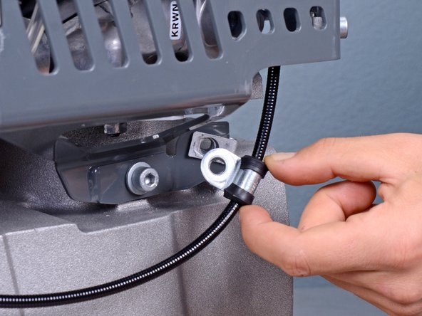
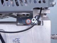
    • Use a 6 mm hex socket to remove the engine guard bolt securing the cable guide.

  15. Motor and Crankcase Separation: crwdns2935265:015crwdnd2935265:01crwdnd2935265:02crwdne2935265:0 Motor and Crankcase Separation: crwdns2935265:015crwdnd2935265:02crwdnd2935265:02crwdne2935265:0
    • Pull the cable guide away from the engine guard.

  16. Motor and Crankcase Separation: crwdns2935265:016crwdnd2935265:01crwdnd2935265:02crwdne2935265:0 Motor and Crankcase Separation: crwdns2935265:016crwdnd2935265:02crwdnd2935265:02crwdne2935265:0
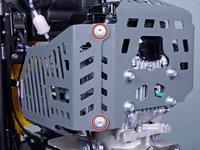
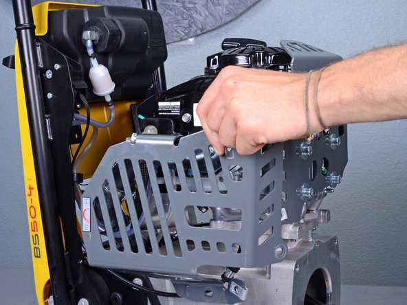
    • Use a 6 mm hex socket to remove the three remaining bolts securing the engine guard: two on the outer edge and one near the crankcase.

  17. Motor and Crankcase Separation: crwdns2935265:017crwdnd2935265:01crwdnd2935265:02crwdne2935265:0 Motor and Crankcase Separation: crwdns2935265:017crwdnd2935265:02crwdnd2935265:02crwdne2935265:0
    • Remove the engine guard.

  18. Motor and Crankcase Separation, Remove the motor nuts: crwdns2935265:018crwdnd2935265:01crwdnd2935265:03crwdne2935265:0 Motor and Crankcase Separation, Remove the motor nuts: crwdns2935265:018crwdnd2935265:02crwdnd2935265:03crwdne2935265:0 Motor and Crankcase Separation, Remove the motor nuts: crwdns2935265:018crwdnd2935265:03crwdnd2935265:03crwdne2935265:0
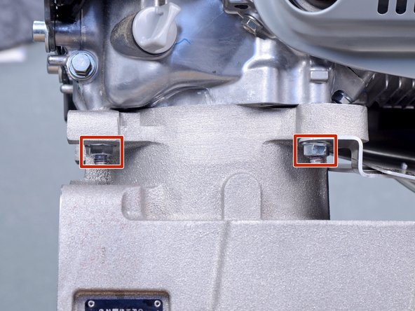
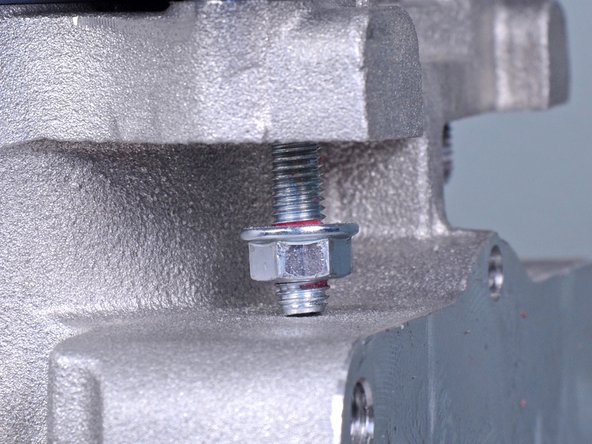
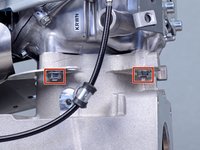
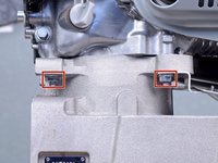
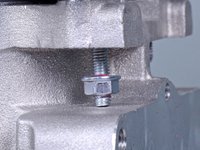
    • Use a 13 mm wrench to remove the four nuts securing the motor to the crankcase, two on each side.

    • When removing the nuts, the crankcase bolts may also become unthreaded, preventing its accompanying nut from being removed. This is fine.

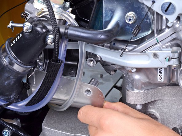
  19. Motor and Crankcase Separation, Move the muffler shroud: crwdns2935265:019crwdnd2935265:01crwdnd2935265:01crwdne2935265:0
    • Use a 10 mm socket to remove the bolt securing the muffler shroud.

  20. Motor and Crankcase Separation: crwdns2935265:020crwdnd2935265:01crwdnd2935265:02crwdne2935265:0 Motor and Crankcase Separation: crwdns2935265:020crwdnd2935265:02crwdnd2935265:02crwdne2935265:0
    • Lower the muffler shroud away from the motor, down onto the crankcase.

    • Do not fully remove the muffler shroud.

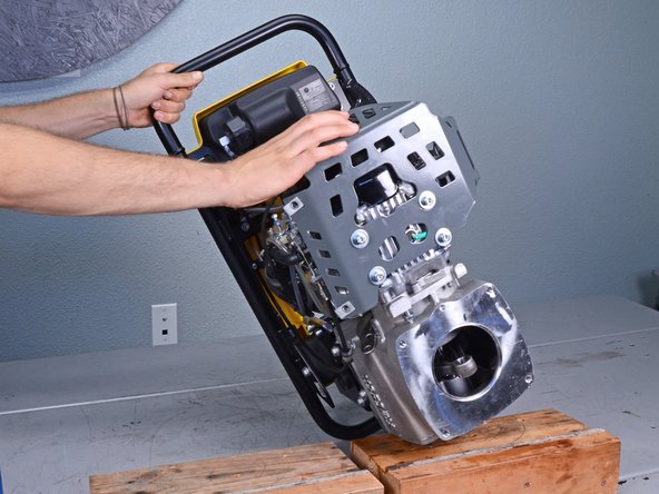
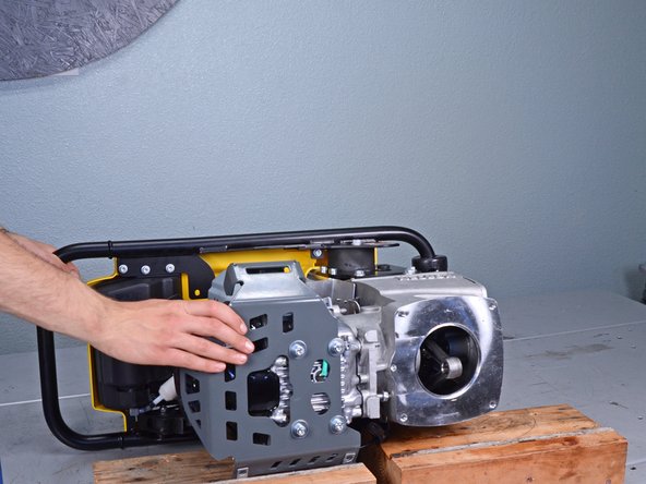
  21. Motor and Crankcase Separation, Separate the motor from the crankcase: crwdns2935265:021crwdnd2935265:01crwdnd2935265:03crwdne2935265:0 Motor and Crankcase Separation, Separate the motor from the crankcase: crwdns2935265:021crwdnd2935265:02crwdnd2935265:03crwdne2935265:0 Motor and Crankcase Separation, Separate the motor from the crankcase: crwdns2935265:021crwdnd2935265:03crwdnd2935265:03crwdne2935265:0
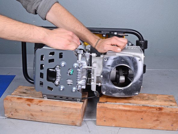
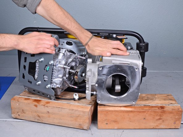
    • Tilt the device down onto its side, supporting both the crankcase and motor with blocks of wood.

    • The motor is loose from the crankcase, so support the motor as you lower the device down.

  22. Motor and Crankcase Separation: crwdns2935265:022crwdnd2935265:01crwdnd2935265:03crwdne2935265:0 Motor and Crankcase Separation: crwdns2935265:022crwdnd2935265:02crwdnd2935265:03crwdne2935265:0 Motor and Crankcase Separation: crwdns2935265:022crwdnd2935265:03crwdnd2935265:03crwdne2935265:0
    • Hold the crankcase steady and pull the motor directly away from it.

    • Ensure each half stays adequately supported.

    • The motor is still attached to the rest of the device via various hoses and cables, so don't attempt to completely remove it.

crwdns2915888:0crwdne2915888:0

To reassemble your device, follow these instructions in reverse order.

Carsten Frauenheim

crwdns2935283:003/10/20crwdne2935283:0

141,765 crwdns2915208:0crwdne2915208:0

crwdns2935297:0422crwdne2935297:0

crwdns2915084:0crwdne2915084:0

iFixit crwdns2935289:0iFixitcrwdne2935289:0

Staff

crwdns2931471:0120crwdne2931471:0

crwdns2935297:020,069crwdne2935297:0

crwdns2947412:00crwdne2947412:0

crwdns2917038:0crwdne2917038:0

crwdns2936625:0crwdne2936625:0:

crwdns2936751:024crwdne2936751:0 0

crwdns2936753:07crwdne2936753:0 2

crwdns2936753:030crwdne2936753:0 4

crwdns2942667:0crwdne2942667:0 30