crwdns2942213:0crwdne2942213:0
-
-
Turn off the computer.
-
Take the slide unlocked into position, remove the battery.
-
-
-
Using a Philips #1 screwdriver, unscrew the 5 screws securing the cover.
-
-
-
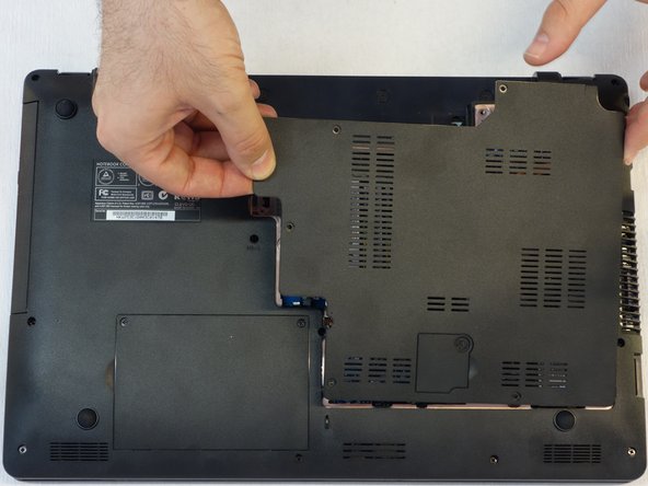
Push the screwdriver a few millimeters under the cover so that it can be touched with your fingers.
-
Now lift the cover carefully.
-
Attention! Disconnect the ventillator cable so that the cover can be completely removed (see next step).
-
-
-
Since the ventillator is mounted under the cover, its power supply cable must first be disconnected so that the cover can then be completely removed.
-
-
-
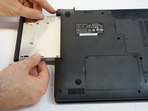
Use a Phillips # 1 screwdriver to screw that holds the CD / DVD drive in place.
-
-
-
Pull the CD / DVD drive carefully out
-
-
-
Use a Phillips # 1 screwdriver to remove the two screws located in the slot of the accumulator.
-
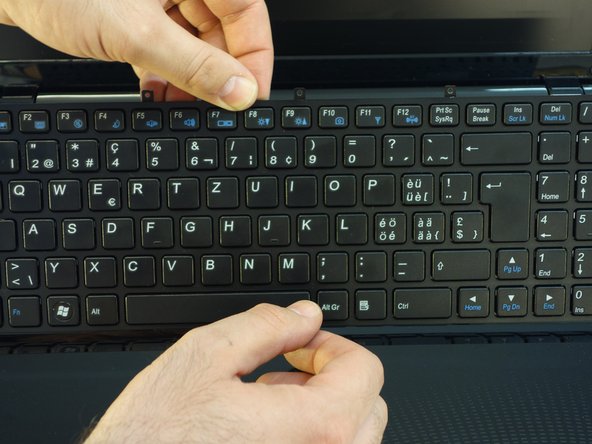
Insert a standard screwdriver into the slot in the cover above the keyboard.
-
Lift the cover with the usual care.
-
-
-
-
Use a Phillips # 1 screwdriver to remove the four screws securing the keyboard in the upper part.
-
-
-
Turn the keyboard towards the screen.
-
Carefully remove the connection cable in the direction of the plug axis.
-
-
-
Disconnect plug A.
-
Disconnect plug B.
-
-
-
Using the Phillips # 1 screwdriver, remove the 16 screws that secure the cover.
-
-
-
Using a Phillips #1 screwdriver, remove all 16 screws that secure the entire cover.
-
-
-
Using a Phillips #1 screwdriver, remove all 16 screws that secure the entire cover.
-
-
-
Using a Phillips #1 screwdriver, remove all 16 screws that secure the entire cover.
-
-
-
Using a Phillips #1 screwdriver, remove the other screw located on the back.
-
Remove the connector for the touchpad.
-
-
-
To remove the keyboard frame, start with the upper part on the right. (Visual access to the clips through the opening of the CD/DVD drive) by inserting a small normal screwdriver or better a small guitar pick
-
Then continue with the lower part.
-
-
-
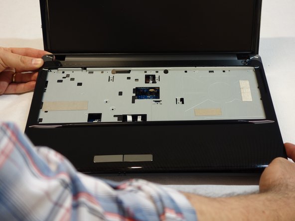
Proceed with the removal of the keyboard bezel in the clockwise direction.
-
Remove the keyboard frame and the motherboard appears.
-
-
-
Unplug the main connector.
-
Unplug the small connector in the middle.
-
-
-
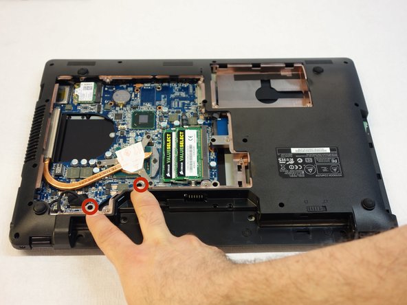
Turn the computer over and unplug the connector near the processor (CPU).
-
Remove the other connector that is immediately to the right of it.
-
Using a Philips #1 screwdriver, remove the 2 mounting screws of the Wi-Fi chipset.
-
-
-
Unplug the plug that is positioned in the back
-
Disconnect the small connector that is right next to the first connector.
-
With a Philips #1 screwdriver, remove the screws outlined in red.
-
-
-
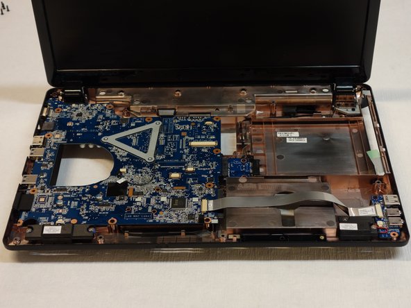
Using a Philips #1 screwdriver, remove the 10 mounting screws from the motherboard.
-
Disconnect the small connector that is located in the front.
-
With a Philips #1 screwdriver, remove the 2 screws that are crosswise and marked with blue circles.
-
Take out the motherboard.
-


For reassembly, follow the instructions in reverse order.
For reassembly, follow the instructions in reverse order.
crwdns2934873:0crwdne2934873:0
100%


crwdns2934885:0crwdne2934885:0 crwdns2934875:0crwdne2934875:0
crwdns2934877:0crwdne2934877:0 ›