crwdns2915892:0crwdne2915892:0
This guide will aid you in the replacement of the logic board in the speaker.
crwdns2942213:0crwdne2942213:0
-
-
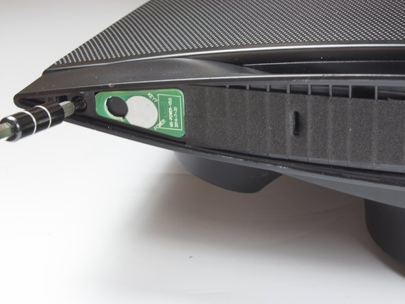
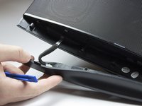
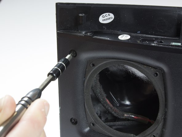
Use a spudger or your fingers to pry off and remove the rubber pad on the bottom of the speaker.
-
-
-
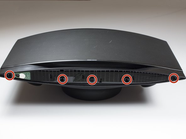
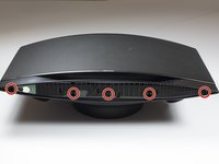
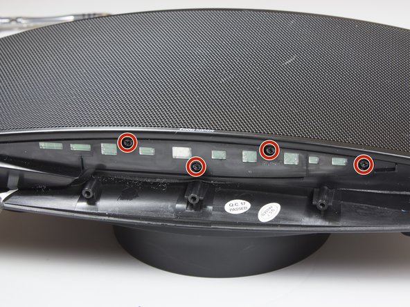
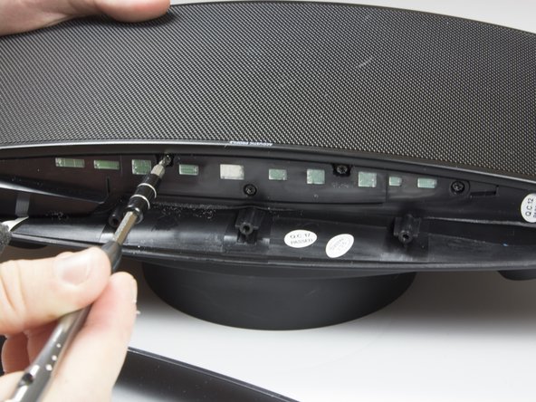
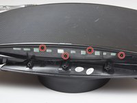
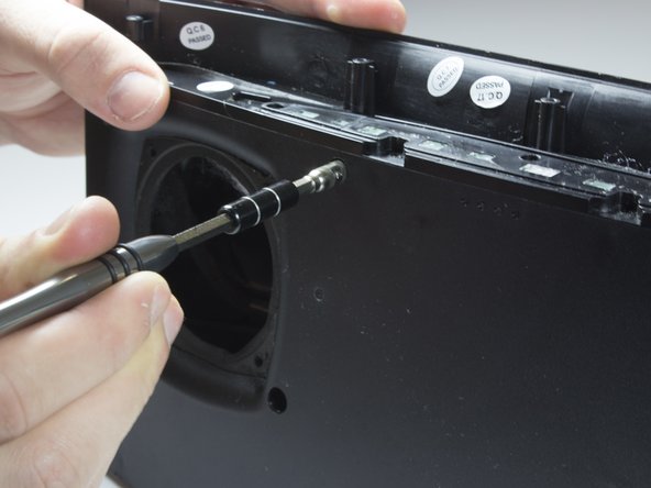
Remove the five 10mm screws with a TR 10 screwdriver.
-
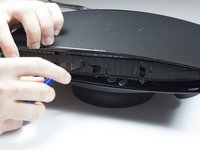
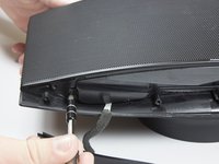
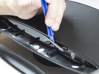
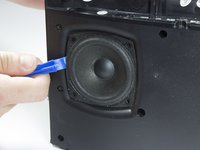
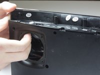
Use a spudger to break the remaining adhesive holding the grille to the speaker body.
-
-
-
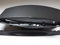
Flip speaker around and use a plastic opening tool to remove the top panel from the speaker.
-
-
-
Use a plastic opening tool to remove the foam and uncover four more screws.
-
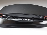
Use a TR 10 screwdriver to remove the five 10mm screws on the top of the speaker.
-
-
-
Use a TR 10 screwdriver to remove two of the 10mm screws that secure the speaker grille.
-
-
-
With the top panel removed, use a spudger to remove the display panel.
-
Use a TR 10 screwdriver to remove the four final 10mm screws securing the speaker grille.
-
-
-
-
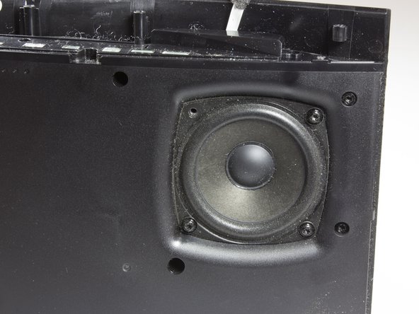
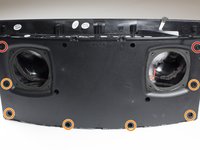
After removing grille, you will see the speakers.
-
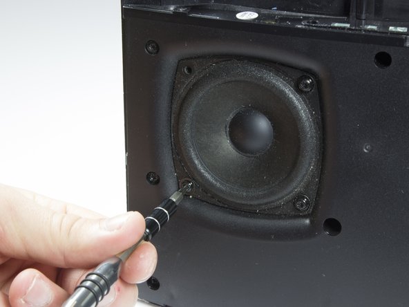
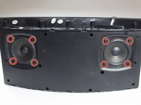
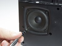
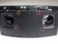
Remove the eight 10mm screws that surround the speakers. There will be four around each speaker.
-
-
-
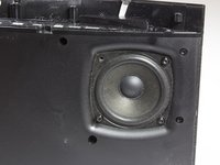
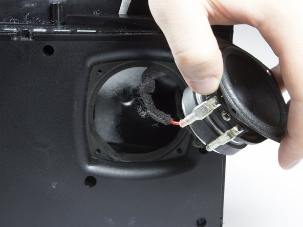
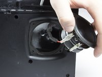
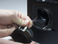
Carefully lift each speaker from the housing. It may be necessary to break a light adhesive seal.
-
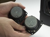
Set each speaker beside the main housing.
-
-
-
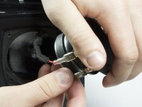
Carefully but firmly unplug the two wires from each driver.
-
The front speakers can now be removed.
-
-
-
Identify the eight screws around the border of the front panel.
-
Using the TR 10 driver, remove the two 8mm screws.
-
Using the TR 10 driver, remove the six 12mm screws.
-
-
-
Use a 5 mm hex driver to extend the TR 10 driver. This allows the driver to access screws with deeper countersinks.
-
-
-
Identify the remaining four screws in the front panel.
-
Use the extended driver from the previous step to remove the four 12mm TR 10 screws.
-
-
-
Gently pull the front panel away from the back panel.
-
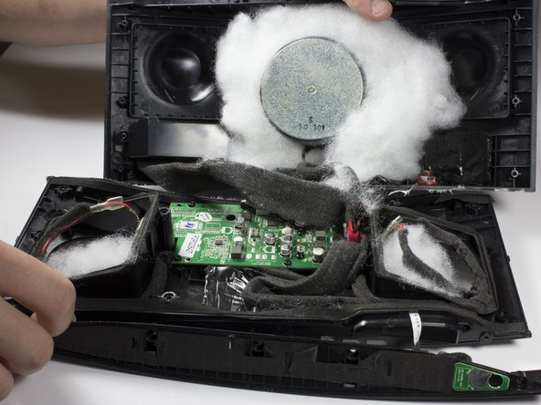
Remove the white sound dampening material from the speaker. Note the location of the material and set aside.
-
-
-
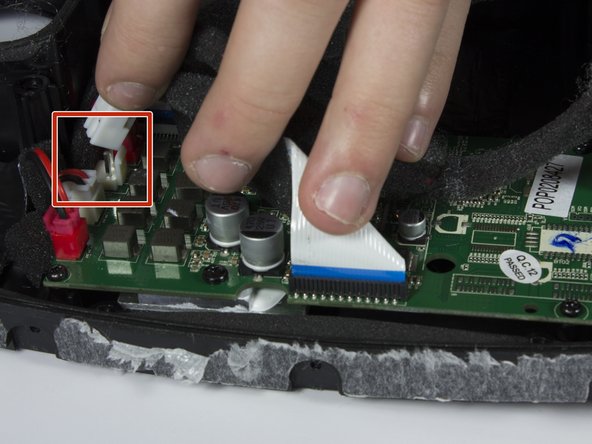
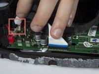
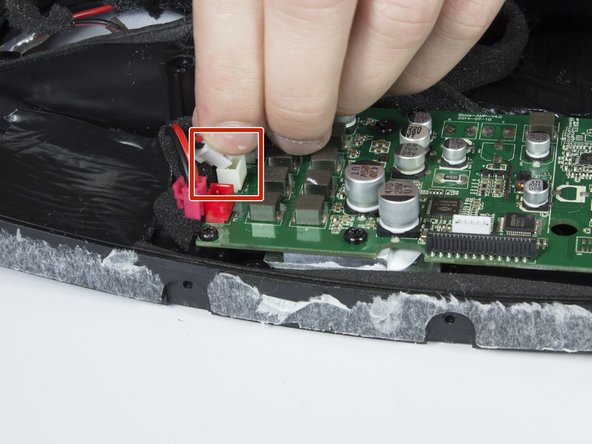
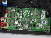
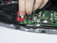
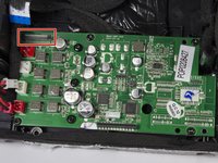
Unplug the rear white connector from the logic board.
-
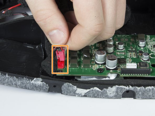
Unplug the rear red connector beside the white one.
-
-
-
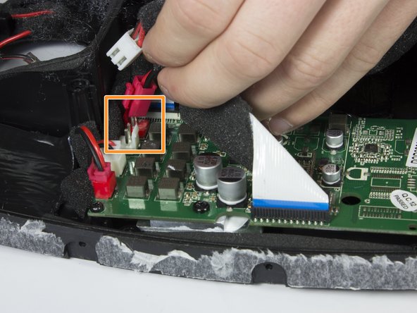
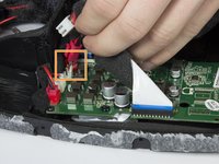
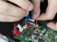
Unplug the front white connector from the logic board.
-
Unplug the rear white connector from the logic board.
-
-
-
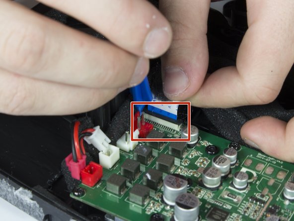
Remove the front ribbon cable from the logic board.
-
-
-
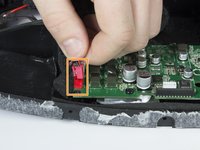
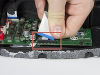
Use a plastic opening tool to lift the brown ribbon cable retainer clip.
-
The ribbon cable can now be removed from the logic board.
-
-
-
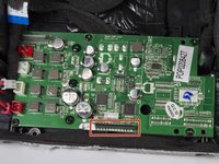
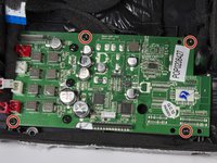
Use a TR 10 driver to remove the four 10mm screws that secure the logic board to the front panel.
-
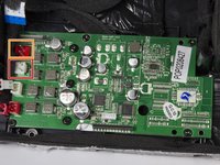
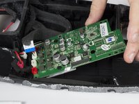
Remove the logic board from the speaker.
-


To reassemble your device, follow these instructions in reverse order.
To reassemble your device, follow these instructions in reverse order.
crwdns2935221:0crwdne2935221:0
crwdns2935229:03crwdne2935229:0
crwdns2915084:0crwdne2915084:0

Cal Poly, Team 21-5, Maness Winter 2017 crwdns2935289:0Cal Poly, Team 21-5, Maness Winter 2017crwdne2935289:0
CPSU-MANESS-W17S21G5
crwdns2931471:04crwdne2931471:0
crwdns2935297:012crwdne2935297:0
crwdns2947412:02crwdne2947412:0
Monster Soundstage circuit board supplier?
@shughe11 Monster Soundstage circuit board supplier?