crwdns2942213:0crwdne2942213:0
-
-
-
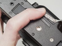
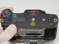
Push down the latch to release the film door.
 crwdns2952109:0crwdne2952109:0
-
-
-
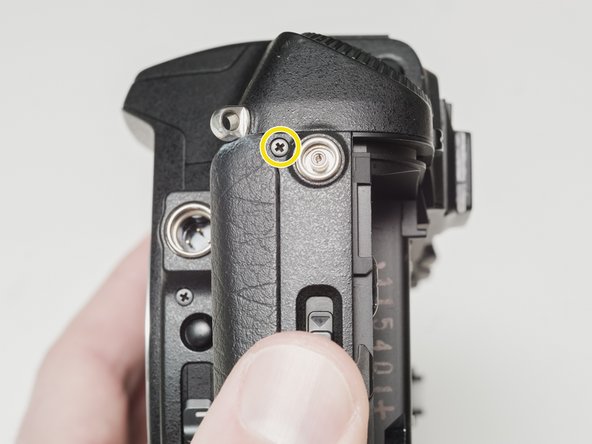
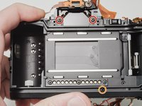
Remove two 7.5 mm #00 screws.
-
Remove one 9.0 mm #00 screw.
-
Remove one 13.5 mm #00 screw from inside the battery compartment.
-
-
-
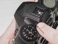
Push the button to pop up the flash.
-
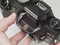
Remove one 3.5 mm #00 screw.
-
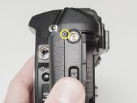
Remove one 5.5 mm #00 screw.
-
-
-
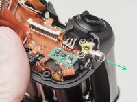
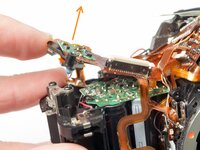
Carefully lift the top cover away from the body to access wired connections.
-
-
-
Peel back the corner of the rubber grip.
-
Remove the small plastic cover.
-
-
-
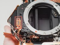
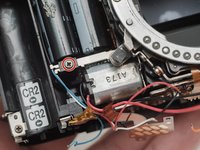
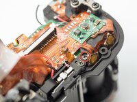
Use a 1kΩ-10kΩ high power resistor to discharge the capacitor. Place the resistor between the blue wire, exposed in the previous step, and ground.
-
-
-
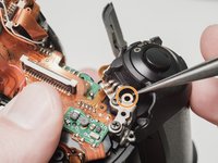
Carefully lift the sides of the white latch.
-
-
-
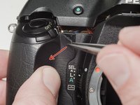
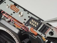
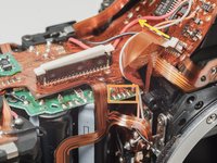
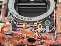
Desolder the red wire.
-
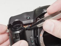
Carefully lift the sides of the white latch.
-
-
-
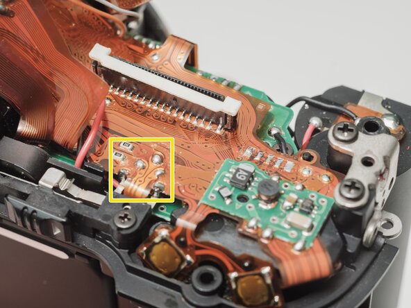
Desolder blue, black, brown and green wires.
-
Remove the loose shim washer if present.
-
-
-
-
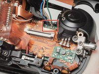
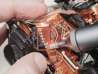
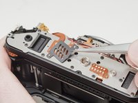
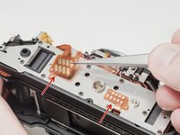
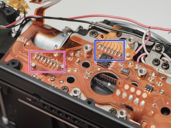
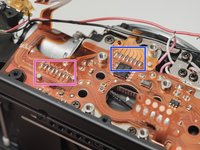
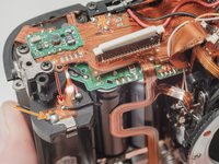
Remove the piece of cellophane tape covering the flex connections.
-
Desolder flex connetions.
-
-
-
-
-
Use isopropyl alcohol to soften the adhesive under the country plate and remove.
-
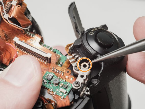
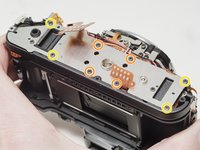
Remove one 5mm #00 screw.
-
Remove one 7.5mm #00 screw.
-
Remove two 4.5mm #00 screws.
-
Remove one 5.5mm #00 screw.
-
Remove the plastic frame around the accessory grip contacts.
-
-
-
Remove one 4.0 mm #00 screw.
-
Remove left cover.
-
-
-
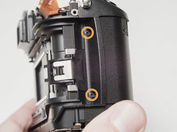
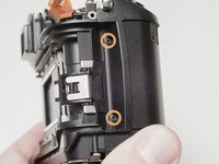
Remove one 6.0 mm #00 screw.
-
Remove two 3.5 mm #00 screws.
-
Remove one 5.0 mm #00 screw.
-
Remove the strap lug.
-
-
-
Carefully pull the right panel away from the body. It is still attached.
-
Desolder the flex connections.
-
-
-
-
-
Remove the protective mask around the accessory grip contacts.
-
Lift the flex contacts free of their retaining posts. Use isopropyl alcohol to soften any glue or tape that is present.
-
Remove four 4.0 mm #00 screws (standard metric threads).
-
Remove four 4.0 mm #00 screws (plastic threads).
-
-
-
Desolder the black and red wires for the speaker.
-
-
-
Desolder the white and pink wires.
-
Desolder the red, black and gray wires.
-
Desolder the red, black and orange wires.
-
Desolder the white and blue wires.
-
Carefully peal the tape away and detach the red, black, white and blue wires from the glue. Use isopropyl alcohol to soften the glue if necessary.
-
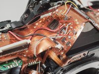
Desolder the flex connection.
-
Desolder the flex connection.
-
-
-
Desolder red, black, gray and orange wires.
-
Desolder flex contacts.
-
Disconnect flex connector.
-
Desolder yellow and purple wires.
-
-
-
Desolder black wire.
-
Desolder battery contact tab.
-
Desolder flex contacts.
-
-
-
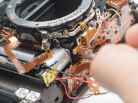
Desolder flex connection and remove from retention posts. Use isopropyl alcohol to soften the glue if necessary.
-
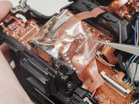
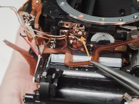
Carefully peal the flex cable from the surface of the flash capacitor. Use isopropyl alcohol to soften the glue if necessary.
-
-
-
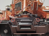
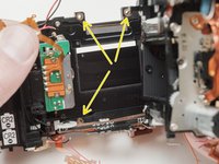
Remove two 5.0 mm #00 screws.
-
Remove the eye piece.
-
-
-
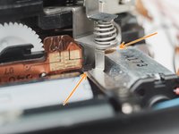
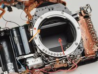
Rotate the black gear downward until the mirror flips up into the taking position. It may take several turns.
-
-
-
Remove one 4.0 mm screw.
-
Gently lift the flex circuit away from the housing.
-
-
-
Remove two 6.5 mm #0 screws.
-
Remove one 8.0 mm #0 screw.
-
Remove one 4.0 mm #00 screw.
-
Remove one 4.5 mm #00 screw.
-
Remove two 2.5 mm #00 screws.
-
There may be a shim washer here. Remove if loose.
-
Remove one 4.0 mm #00 shoulder screw.
-
-
-
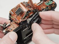
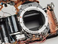
Push the mirror box up to free it from the bottom plate.
-
Lift the left side of the mirror box and rotate it up and out of the camera body.
-
Check for shim washers at the mount locations. Note location and remove if loose.
-
-


To reassemble your device, follow these instructions in reverse order.