crwdns2915892:0crwdne2915892:0
Follow this guide to build a portable oscilloscope using the Mini Digital Oscilloscope DIY Soldering Kit. This kit is designed for individuals looking to advance their surface-mount soldering skills, and isn't suitable for beginners. If this is your first time soldering, we'd recommend starting with a beginner-friendly kit.
If you'd like to read up on soldering techniques before diving in, check out our guide on soldering and desoldering connections.
crwdns2942213:0crwdne2942213:0
-
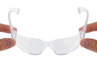
crwdns2935267:0crwdne2935267:0iFixit Safety Glasses$3.99
-
If you're working indoors, place your fume extractor next to your project. Set up your tools in a well-lit area, away from anything flammable:
-
A pair of safety glasses (solder spatter will damage regular glasses)
-
A soldering iron and solder (leaded or lead-free)
-
A pair of angled tweezers
-
A tip cleaning tool (damp cellulose sponge or brass wool)
-
A pair of flush cutters
-
A desoldering pump and/or solder wick (aka desoldering braid), in case you make a mistake.
-
(Optional) A silicone work mat to prevent damage to your work surface.
-
-
-
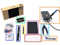
Your oscilloscope kit contains the following parts:
-
Circuit board
-
Case
-
Microcontroller (aka CPU)
-
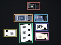
Resistors & capacitors
-
Power inductor
-
External interfaces
-
OLED display and display connectors
-
-
-
LED
-
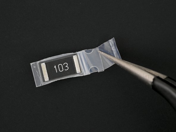
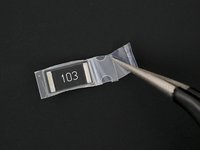
1W/10 kΩ (103) resistor
-
10 kΩ (103) resistor
-
2 kΩ (202) resistors
-
10 μF capacitor
-
10 nF (103) capacitor
-
22 nF capacitor
-
-
crwdns2935267:0crwdne2935267:0Silicone Work Mat$9.95
-
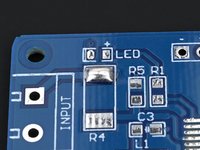
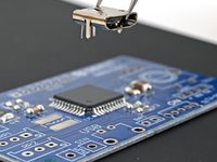
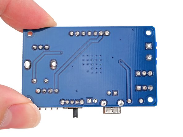
Set down the circuit board on your work mat/surface so the front (the side labeled MiNi-DSO at the top) is facing up.
-
-
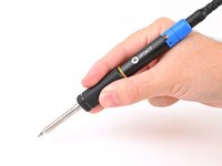
crwdns2935267:0crwdne2935267:0FixHub | Power Series Smart Soldering Iron$79.95
-
Put on your safety glasses.
-
Turn on your soldering iron. If your soldering iron has temperature control:
-
Set it to 300 °C (~570 °F) if you're using leaded solder
-
Set it to 375 °C (~700 °F) if you're using lead-free solder
-
Clean the tip of your soldering iron. If you're using a cellulose sponge, wet the sponge with distilled water until damp and quickly wipe the tip across it. If you're using brass wool, stab the tip into the wire a few times.
-
Melt a small glob of solder onto the tip of the iron. This is called "tinning the tip" and will help with heat transfer.
-
-
-
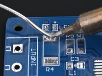
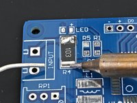
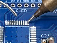
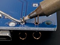
Press the iron's tip against one of the solder pads in the outline labeled R4 for a few seconds to heat it.
-
Feed the solder wire into the heated area until there's a small glob of solder on the pad.
-
Remove the solder wire first, then remove the soldering iron from the pad.
-
-
-
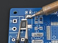
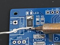
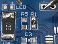
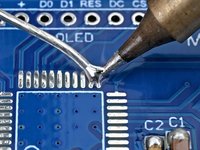
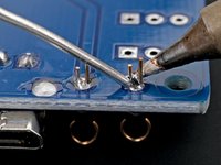
Place the largest 10 kΩ resistor (labeled 103) in the outline labeled R4 on the board.
-
Re-heat the solder while holding the resistor in its outline until the molten solder envelops the end (shiny) cap.
-
Remove the iron, then remove the tweezers once the solder has cooled.
-
-
-
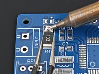
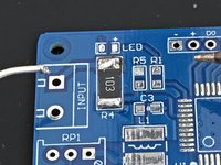
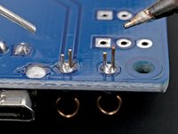
Press the tip against the second R4 solder pad and the resistor's second end cap for a few seconds to heat them both. Angle the tip so it has maximum contact with the pad and cap.
-
Feed the solder wire into the heated area until there's a small glob of solder surrounding the end cap.
-
Remove the solder wire first, then remove the soldering iron from the pad.
-
-
-
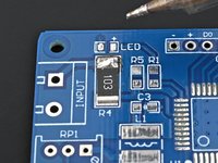
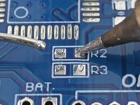
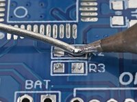
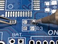
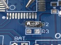
Press the iron's tip against one of the board's R2 solder pads for a few seconds to heat it.
-
Feed the solder wire into the heated area until there's a small glob of solder on the pad.
-
-
-
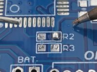
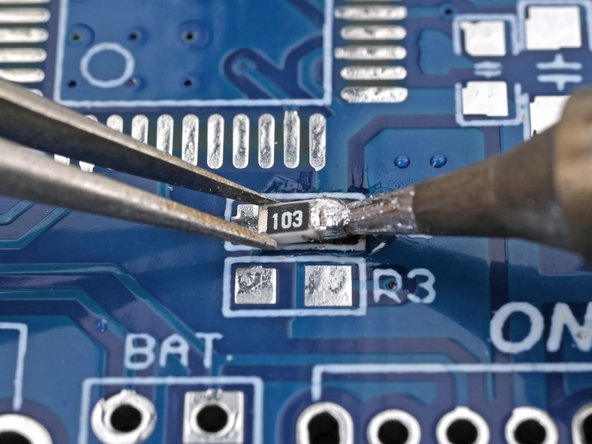
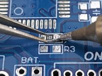
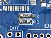
Place the smaller 10 kΩ resistor (labeled 103) in the outline labeled R2 on the board.
-
Press the soldering iron's tip onto the edge of the solder pad while holding the resistor in its outline, so that its end caps (the shiny parts) are resting on the circuit board's pads.
-
Remove the iron, then remove the tweezers once the solder has cooled.
-
-
-
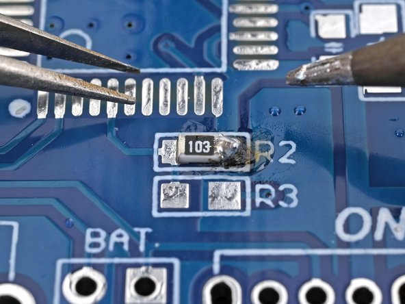
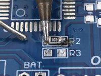
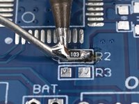
Press the tip against the second R2 solder pad and the resistor's second end cap for a few seconds to heat them both. Angle the tip so it has maximum contact with the pad and cap.
-
Feed the solder wire into the heated area until there's a small glob of solder surrounding the second end cap.
-
-
-
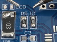
Repeat this process to solder the three 2 kΩ resistors (labeled 202) in the outlines labeled R3, R1, and R5 on the front of the board.
-
-
-
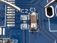
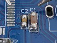
Repeat the process to solder the three capacitors to the front of the board:
-
The large capacitor in the outline labeled C1
-
The capacitor labeled 103 on its packaging in the outline labeled C2
-
The 22 nF capacitor (with no label on its packaging) in the outline labeled C3
-
-
-
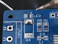
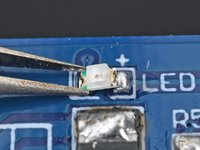
Press the iron's tip against the circuit board's LED solder pad for a few seconds to heat it, then feed the solder wire into the heated area until there's a small glob of solder on the pad.
-
Place the LED in the outline labeled LED on the board, with the white (non-green) side aligned with the "+" symbol.
-
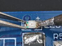
Solder the LED's first end cap to the board.
-
-
-
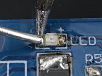
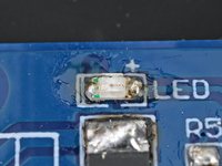
Press the tip against the second LED solder pad and feed the solder wire into the heated area until there's a small glob of solder contacting the end cap.
-
Remove the solder wire first, then remove the soldering iron from the pad.
-
-
-
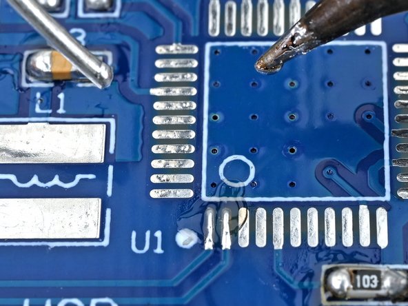
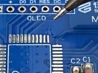
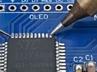
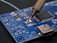
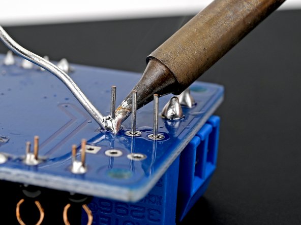
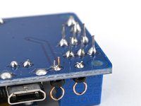
Press the iron's tip against the board's bottom left microcontroller solder pad for a few seconds to heat it.
-
Feed the solder wire into the heated area until there's a small glob of solder on the pad.
-
-
-
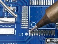
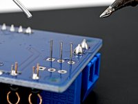
Repeat the last step to apply solder to the board's top right microcontroller solder pad.
-
-
crwdns2935267:0crwdne2935267:0Tweezers$3.99
-
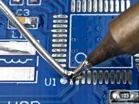
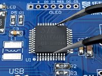
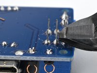
Orient the microcontroller with its outline (labeled U1) on the circuit board, so the circle on microcontroller is on top of the circle on the board.
-
Align all 44 pins are aligned with their respective pads on the board.
-
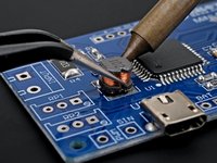
Hold the microcontroller still with tweezers and re-heat the solder from the last two steps to solder it to the board.
-
-
-
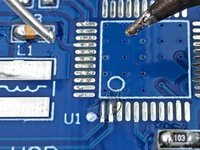
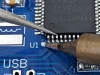
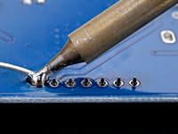
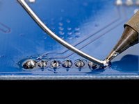
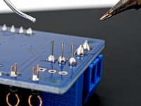
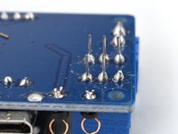
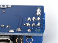
Press the tip against another solder pad and feed the solder wire into the heated area until there's a small solder joint on the pin.
-
Repeat this process for all of the remaining microcontroller pins.
-
-
-
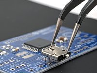
Align the USB port with the outline labeled USB on the front of the board.
-
Insert the leads of the USB port into their four holes on the board, so it sits flush.
-
-
-
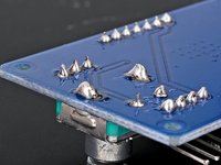
Flip the board over so the pins are facing up.
-
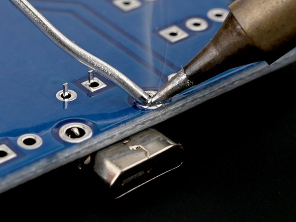
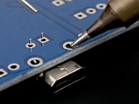
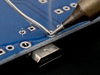
Press down with the tip of your iron on the one of the USB port's solder pads closest to the edge and solder the USB port's first pin.
-
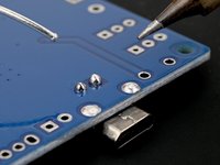
Solder the remaining USB port pins.
-
-
-
-
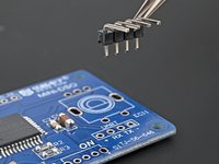
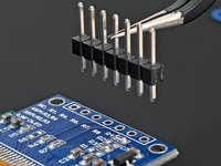
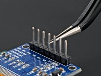
Align the UART connector with the outline labeled UART on the front of the board.
-
Insert the shorter pins of the UART connector into their four holes on the board, so it sits flush.
-
-
-
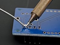
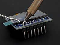
Flip the board over so the pins are facing up.
-
Solder the UART connector to the board.
-
-
-
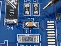
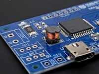
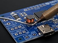
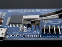
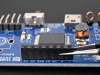
Press the iron's tip against the circuit board's L1 solder pad for a few seconds to heat it, then feed the solder wire into the heated area until there's a small glob of solder on the pad.
-
Re-heat the solder while holding the inductor in its outline, so that its end caps (the sides with the notches) are resting on the circuit board's pads.
-
Remove the iron, then remove the tweezers once the solder has cooled.
-
-
-
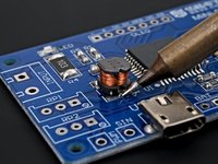
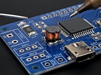
Press the tip against the power inductor's second solder pad and the power inductor's second end cap for a few seconds to heat them both. Angle the tip so it has maximum contact with the pad and cap.
-
Feed the solder wire into the heated area until there's a small glob of solder joining the second end cap to its pad.
-
-
-
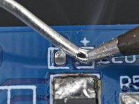
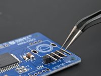
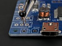
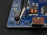
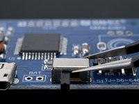
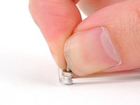
Use tweezers to pick up one of the test rings and squeeze its leads together.
-
Insert the test ring leads into the hole labeled PWM on the front of the board.
-
-
-
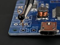
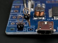
Repeat this process for the other test ring in the hole labeled SIN.
-
-
-
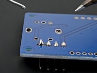
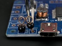
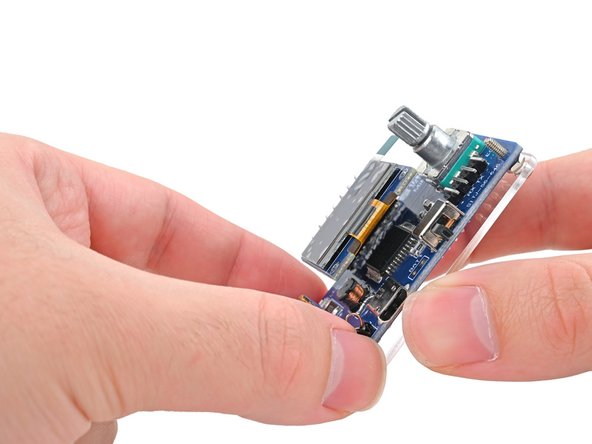
Flip the board over so the test rings' leads are facing up.
-
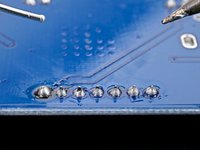
Solder the test rings to the board.
-
-
-
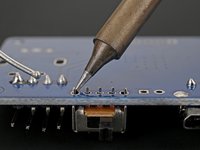
Align the toggle switch with the outline labeled ON on the front of the board, with the switch itself facing outwards.
-
Insert the switch's five pins into their holes in the board.
-
-
-
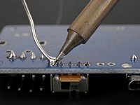
Flip the board so the toggle switch's pins are facing up.
-
Solder the toggle switch to the board.
-
-
-
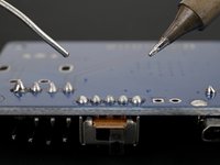
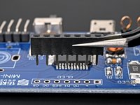
Align the OLED female header strip with the outline labeled OLED on the board.
-
Insert the header's seven pins into their holes in the board.
-
-
-
Flip the board over so the header strip's pins are facing up.
-
Solder the female header strip to the board.
-
-
-
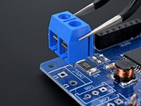
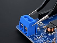
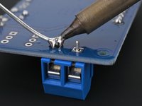
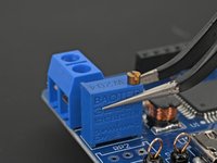
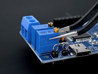
Align the terminal block with the outline labeled INPUT on the front of the board, with the terminal interface facing outwards.
-
Insert the block's two pins into their holes in the board.
-
-
-
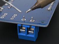
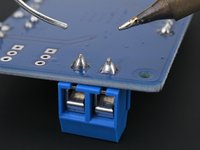
Flip the board over so the terminal block's pins are facing up.
-
Solder the terminal block to the board.
-
-
-
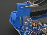
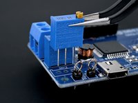
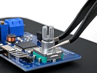
Align the first adjustable resistor (labeled W204 on the top) with the outline labeled RP1 on the front of the board. The gold knob should be closest to the microcontroller.
-
Insert the resistor's three pins into their holes in the board.
-
-
-
Flip the board over so the resistor's pins are facing up.
-
Solder the first adjustable resistor to the board.
-
-
-
Align the second adjustable resistor (labeled W501 on the top) with the outline labeled RP2 on the front of the board. The gold knob should be closest to the microcontroller.
-
Insert the resistor's three pins into their holes in the board.
-
-
-
Flip the board over so the resistor's pins are facing up.
-
Solder the second adjustable resistor to the board.
-
-
-
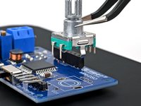
Align the encoder knob with the outline labeled EC11 on the front of the board. Orient it so the three leads at the top correspond with the three holes on the board under the MiNi-DSO label.
-
Insert the encoder's seven pins into their holes in the board.
-
-
-
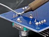
Flip the board over so the encoder's pins are facing up.
-
Solder the encoder knob to the board.
-
-
-
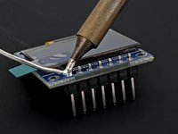
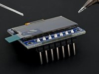
Align the male OLED display connector into the outline on the back of the display board. The shorter pins should be facing the board.
-
Insert the connector's seven shorter pins into their holes in the board.
-
-
-
Flip the display board over so the connector's leads are facing up.
-
Solder the OLED display connector to the display board.
-
-
-
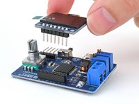
Align the display's male pins with its female connector on the front of the board, so the display itself is over the microcontroller.
-
Push the pins fully into the connector.
-
-
-
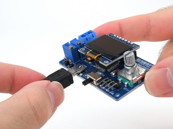
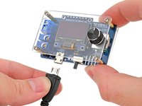
Connect the oscilloscope to a power source with the included Micro USB cable.
-
-
-
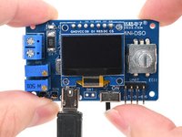
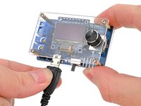
If your toggle switch is off, slide it to the ON position to power up your oscilloscope. You should see the display turn on and show "MiniDSO" at the top.
-
-
-
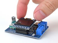
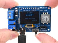
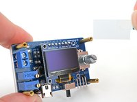
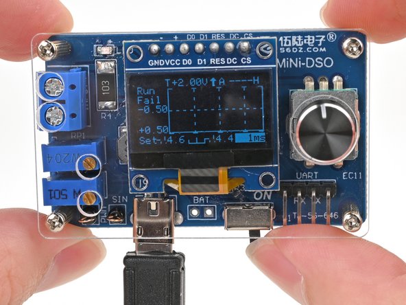
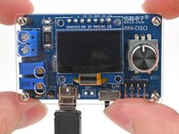
Once the oscilloscope boots up, you should see a screen with a graph. Rotate the encoder knob to test its functionality.
-
Turn off the oscilloscope and unplug its USB cable once you've verified its functionality.
-
-
-
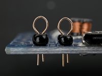
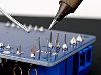
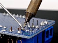
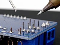
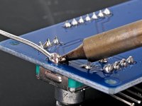
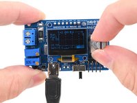
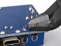
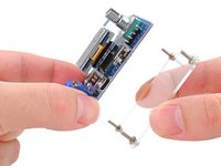
Use your flush cutters to trim the test ring leads until they're no longer poking up past the solder joint from the back of the board.
-
-
-
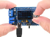
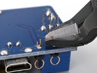
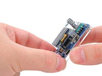
Repeat the last step to trim all the leads until they're no longer poking up past their solder joint from the back of the board.
-
-
-
The case contains the following parts:
-
1x Bottom acrylic
-
1x Top acrylic
-
4x 11 mm screws
-
4x 7 mm screws
-
4x Nuts
-
4x Standoff posts
-
-
-
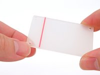
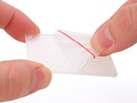
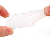
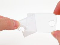
Use your fingernail or tweezers to peel up an edge of the bottom acrylic's protective film and peel it off.
-
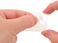
Repeat this process for the film on the other side.
-
-
-
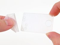
Repeat the previous step to remove the top acrylic's protective films.
-
-
-
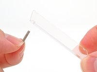
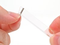
Insert one of the 11 mm screws into a hole in the bottom acrylic.
-
-
-
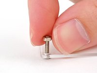
Thread one of the nuts onto the screw until it's finger-tight.
-
-
-
Repeat this process for the remaining three holes in the bottom acrylic.
-
-
-
Align the circuit board's four corner holes with the screws protruding from the bottom acrylic. Orient the board so the back is facing the bottom acrylic.
-
Insert the four screws through their holes until the board sits flush with the nuts on the bottom case.
-
-
-
Thread one of the standoff posts onto a screw protruding from the board until it's finger-tight against the board.
-
Repeat this process for the other three standoff posts & screws.
-
-
-
Grab the plastic pull tab on the OLED display's protective film and peel it off.
-
-
-
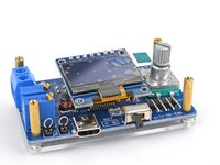
Align the top acrylic with the four standoff posts' screw holes, the adjustable resistor knobs, and the terminal block screws.
-
-
-
Use a screwdriver to screw one of the 7 mm screws into a standoff post until it's roughly finger-tight.
-
Screw the last three screws into the remaining standoff posts.
-
-
-
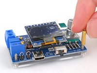
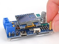
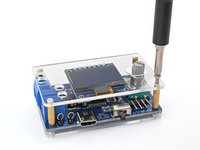
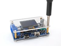
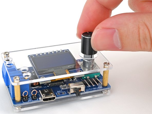
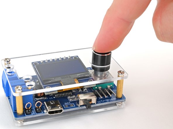
Align the hole in the bottom of the knob cover with the encoder knob.
-
Insert the knob cover onto the encoder knob and push it down until it bottoms out.
-
-
-
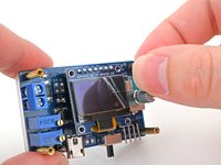
Reconnect the Micro USB cable to the oscilloscope.
-
-
-
Toggle the switch to the ON position to power up your oscilloscope.
-


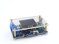


You've taken a great step toward mastering the valuable and versatile skill of surface-mount and through-hole soldering. With this kit under your belt, you're well-equipped to tackle various electronics projects and repairs. Remember, practice makes perfect, so don't hesitate to experiment and refine your techniques.
To learn more soldering skills, click here.
If you need additional help, check out our Answers community.
crwdns2935221:0crwdne2935221:0
crwdns2935229:013crwdne2935229:0

