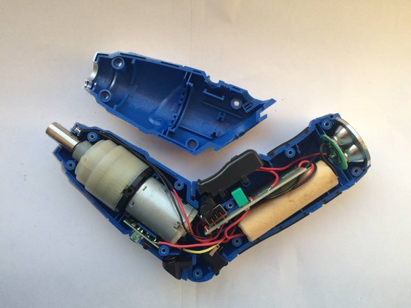
crwdns2915892:0crwdne2915892:0
This budget cordless screwdriver was sold in the UK by Maplin (no longer trading) but the same or very similar products have very likely been sold under different brandings.
As an entry level device, it does not contain a torque-limiting clutch and is powered by a single 3.7V 18650 lithium cell.
Disassembly and reassembly are not difficult, but reassembly takes a little patience in order to get everything to fit together properly.
crwdns2942213:0crwdne2942213:0
-
-
Remove 6 screws in the handle.
-
Using a jimmy, thin spatual or other prying tool, separate the two halves of the handle.
-
As you separate the two halves, try not to let the trigger spring take flight. On reassembly, make sure the two pegs on the trigger are fitted into their slots and the spring is in place.
-
As you separate the halves of the handle, the lamp assembly may stay with the upper half you are removing. Transfer it to the lower half for reassembly. Ensure all parts are fitted snugly in their proper positions and that wires are tucked away so as not to be pinched when the handle is closed.
-
If you need to, you can now lift out the circuit board for inspection, or lift out the battery for testing or replacement.
-
-
-
Remove 4 screws in the front section and separate the two halves.
-
You can now lift out the motor and gearbox. If you unsolder the motor connections, note that one of the tags has a small + sign next to it. The red wire connects to this.
-
-
-
The gearbox just lifts off the motor. To reassemble, make sure the gap in the middle of the 3 nylon gears is as large as possible otherwise it will not be possible to insert the gear on the end of the motor shaft between them.
-
The steel disk and the gear on the motor shaft can simply be lifted off.
-
The black plastic piece can be removed from the motor by undoing 2 screws.
-
A replacement motor can be found online from Far Eastern sellers by searching for the part number RS380S-3.6V. Select one with a 6mm shaft.
-
-
-
-
To test the motor, unsolder the connections and attach jumper leads. Touch these very briefly on the terminals of the battery. If the motor fails to turn, disconnect the battery immediately as there may be a short circuit.
-
If you need to disassemble the motor, first make a mark on the steel case next to the terminal marked "+". If you reassemble it the wrong way round the motor will turn in the wrong direction.
-
Prise up the two metal tabs at the back of the steel case. The magnets will resist the rotor being withdrawn, so rather than pulling on the nylon rear piece, push the spindle into and through the front bearing with a very small screwdriver, otherwise you may distort the brush springs.
-
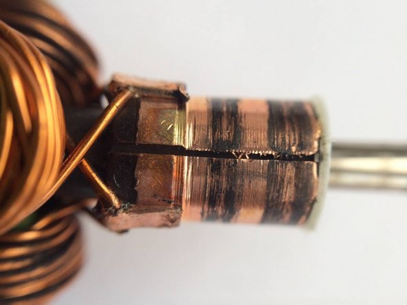
Inspect the commutator with a magnifying glass. Check for any slivers of copper which might be creating a short between any two segments. Clean it with isopropyl alcohol and an old toothbrush.
-
-
-
The circuit board contains the charging and battery protection circuits. At the heart of these is IC1, a 6 pin IC type DWP01-P. This has 3 functions: halting the charge when the battery voltage reaches 4.25V, preventing over-discharge if the battery voltage falls below 2.4V, and over-current protection.
-
A failure to operate or to charge (assuming the battery is good) may be due to this IC or any of the components around it, becoming faulty.
-
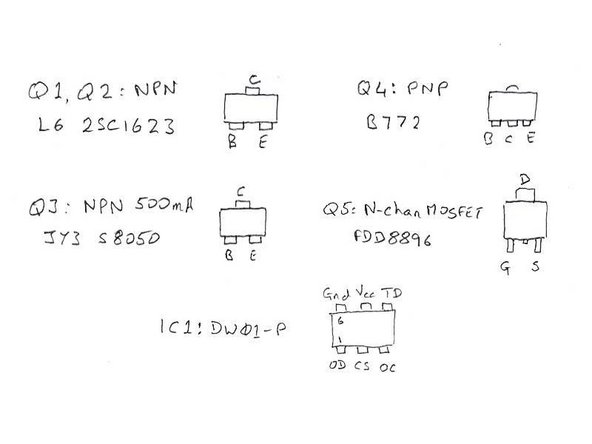
NPN transistors Q1, Q2 and Q3 can be tested with a multimeter on the diode range. First, disconnect the battery. With the positive probe on B and the negative lead on either E or C, it should read around 0.7V.
-
Q4 is a PNP type which can be tested in exactly the same way except with the negative probe on B. Q5 is a N-channel MOSFET and cannot be tested so easily.
-
-
-
The separate circuit shown at the bottom is the charge state indicator in the motor section of the screwdriver.
-
The battery is charged through Q4 and the schottky diode in the charge indicator. When it reaches full charge, IC1 sets its OC output high, turning off Q1 and Q2, and hence Q4.
-
While charging, Q3 is turned on, pulling the gate of Q5 close to ground so turning it off, hence preventing the motor from running.
-
The motor is switched by SW1. However, in the case of the motor stalling or taking excessive current, the voltage on the drain of Q5 will rise, causing the voltage on the CS pin of IC1 to trip its over-current protection. This results in the OD pin going low and turning off the MOSFET Q5.
-
-
-
You may find that when you press the trigger the motor doesn't turn. It may just give a little tick and the front light may flash briefly. With the direction switch in the middle (off) position, the front light lights normally.
-
This is due to the internal resistance of the battery increasing as it ages, even though it may still have plenty of capacity. The initial surge as the motor starts causes the battery voltage to instantaneously drop below the fully discharged voltage. As a result, IC1 disables the motor.
-
The simple fix is to replace the battery with a brand new one, preferably of higher quality, though the quality of lithium batteries you might find for sale is hard to judge.
-
The alternative is a modification to the circuit to prevent the dip in voltage reaching IC1. You will need a surface mount 2.2k resistor and a surface mount 100μF tantalum capacitor.
-
Remove R7 and replace with the 2.2k resistor. Remove C2 and replace with the 100μF tantalum capacitor. The end with the bar on it should be away from the board edge.
-
The tantalum capacitor will be considerably larger than the one you are replacing and so scrape away a little of the solder resist close to the board edge in order to make a new solder pad. Alternatively, use a wire-ended electrolytic capacitor. Positioned carefully on the other side of the board it should still fit within the screwdriver case.
Thanks for the guide, helped me getting an old, but unused, Aldi Top Craft screwdriver going again.
-


To reassemble your device, follow these instructions in reverse order.
To reassemble your device, follow these instructions in reverse order.
crwdns2935221:0crwdne2935221:0
crwdns2935229:06crwdne2935229:0

crwdns2915084:0crwdne2915084:0

Restart Project crwdns2935289:0Restart Projectcrwdne2935289:0
Local Repair Groups
crwdns2931471:024crwdne2931471:0
crwdns2935297:0376crwdne2935297:0
crwdns2947412:05crwdne2947412:0
Usually, these screwdrivers have a cell with low capacity, around 1300mAh. Will the pcb handle a cell with higher capacity? Lets say, a 18650 2.0mAh or higher?
I see no reason why it shouldn’t, in fact it may work better, and be less prone the problem that promted my modification. It’ll just mean that it’ll take longet to charge.
Please do come back and report your experience, and where you got the replacement battery from. My screwdriver has pretty much died again and I was thinking of throwing it out. Perhaps a vape battery would be good - it should be good for a heavy drain application such as this.
I sent so much time trying to figure out the circuit when I came across you article I followed your suggestion and replaced the battery and work ok. You are a legend.
Great guide - but mine has come adrift from the mains charger, and it does not show the voltage/current spec on the unit (shame on them).
So, trying to find the spec of the charger - which you don't give.
I've tried 5v 2A neg earth supplies, but they don't give a recharge.
I have dozens of spare units of varying spec, and it may be one of them ! Please help identify what charger spec is needed.
Hi Steve -
The adapter is 6V 300mA centre positive but since the device contains its own charge regulator it should be fine with anything from 6 - 9V. Any more might be pushing your luck. The label on mine says Model: WJB-Y350600300D.