crwdns2933423:0crwdne2933423:0

Main Board Removal

crwdns2862623:0crwdne2862623:0
crwdns2942641:0crwdne2942641:0

crwdns2942213:0crwdne2942213:0

  1. Main Board Removal, Before you begin: crwdns2935265:01crwdnd2935265:01crwdnd2935265:03crwdne2935265:0 Main Board Removal, Before you begin: crwdns2935265:01crwdnd2935265:02crwdnd2935265:03crwdne2935265:0 Main Board Removal, Before you begin: crwdns2935265:01crwdnd2935265:03crwdnd2935265:03crwdne2935265:0
    • Before starting your repair:

    • Shut down your PlayStation and unplug all cables and accessories.

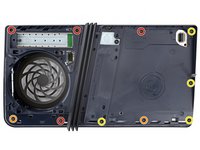
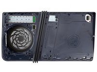
    • Remove any stands supporting your console and lay it down so the right side is facing up.

  2. Main Board Removal, Remove the console covers: crwdns2935265:02crwdnd2935265:01crwdnd2935265:03crwdne2935265:0 Main Board Removal, Remove the console covers: crwdns2935265:02crwdnd2935265:02crwdnd2935265:03crwdne2935265:0 Main Board Removal, Remove the console covers: crwdns2935265:02crwdnd2935265:03crwdnd2935265:03crwdne2935265:0
    • Each console cover is secured with hooks along the rear edge and clips along the front edge.

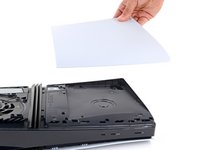
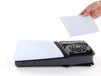
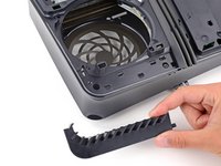
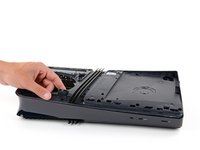
    • To remove a cover, firmly pull up the front edge to release the clips.

    • You'll hear distinct "pops" as the clips release.

    • Remove the cover.

  3. Main Board Removal: crwdns2935265:03crwdnd2935265:01crwdnd2935265:03crwdne2935265:0 Main Board Removal: crwdns2935265:03crwdnd2935265:02crwdnd2935265:03crwdne2935265:0 Main Board Removal: crwdns2935265:03crwdnd2935265:03crwdnd2935265:03crwdne2935265:0
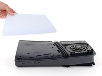
    • Use the same process to remove the three remaining covers.

    • To reinstall a cover, place the hooks into their cutouts along the rear edge and firmly press the front edge of the cover into place to re‑engage the clips.

  4. Main Board Removal, Remove the expansion slot cover screw: crwdns2935265:04crwdnd2935265:01crwdnd2935265:02crwdne2935265:0 Main Board Removal, Remove the expansion slot cover screw: crwdns2935265:04crwdnd2935265:02crwdnd2935265:02crwdne2935265:0
    crwdns2935267:0crwdne2935267:0
    FixMat
    $36.95
    • Throughout this repair, keep track of each screw and make sure it goes back exactly where it came from.

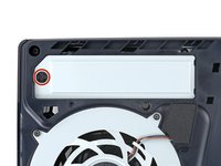
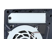
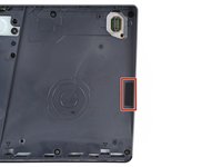
    • Use a Phillips screwdriver to remove the 17.1 mm‑long screw securing the expansion slot cover.

  5. Main Board Removal, Remove the expansion slot cover: crwdns2935265:05crwdnd2935265:01crwdnd2935265:03crwdne2935265:0 Main Board Removal, Remove the expansion slot cover: crwdns2935265:05crwdnd2935265:02crwdnd2935265:03crwdne2935265:0 Main Board Removal, Remove the expansion slot cover: crwdns2935265:05crwdnd2935265:03crwdnd2935265:03crwdne2935265:0
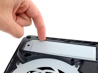
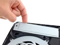
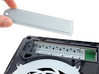
    • Use your fingers to lift the expansion slot cover near the notch by the screw hole and remove it.

  6. Main Board Removal, Remove the fan cables cover: crwdns2935265:06crwdnd2935265:01crwdnd2935265:03crwdne2935265:0 Main Board Removal, Remove the fan cables cover: crwdns2935265:06crwdnd2935265:02crwdnd2935265:03crwdne2935265:0 Main Board Removal, Remove the fan cables cover: crwdns2935265:06crwdnd2935265:03crwdnd2935265:03crwdne2935265:0
    crwdns2935267:0crwdne2935267:0
    Tesa 61395 Tape
    $5.99
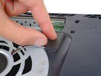
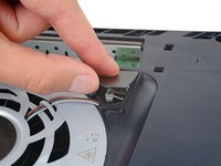
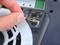
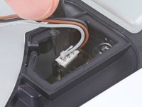
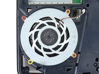
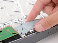
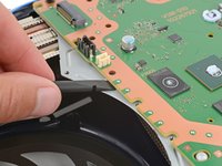
    • Use your fingers to remove the plastic cover hiding the fan cables connector.

    • The cover is secured with light adhesive.

    • During reassembly, press the piece of plastic back into place to secure it with the leftover adhesive. If it isn't sticking, use strips of double-sided tape to secure it.

  7. Main Board Removal, Free the fan cables: crwdns2935265:07crwdnd2935265:01crwdnd2935265:02crwdne2935265:0 Main Board Removal, Free the fan cables: crwdns2935265:07crwdnd2935265:02crwdnd2935265:02crwdne2935265:0
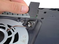
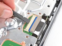
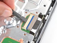
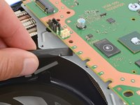
    • Gently pull the fan cables out from under their plastic clip on the frame.

  8. Main Board Removal, Disconnect the fan: crwdns2935265:08crwdnd2935265:01crwdnd2935265:03crwdne2935265:0 Main Board Removal, Disconnect the fan: crwdns2935265:08crwdnd2935265:02crwdnd2935265:03crwdne2935265:0 Main Board Removal, Disconnect the fan: crwdns2935265:08crwdnd2935265:03crwdnd2935265:03crwdne2935265:0
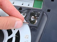
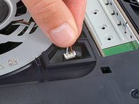
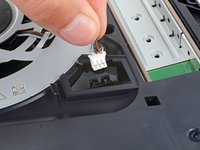
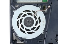
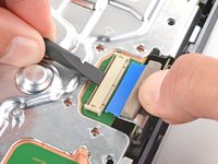
    • Firmly grip the fan cables' white connector head and pull it straight up and out of its socket.

    • If you're having trouble, grip the cables just above the connector head, and gently pull.

    • During reassembly, align the connector over its socket and push down on the edges with the flat end of a spudger until it slides fully into its socket.

  9. Main Board Removal, Remove the fan screws: crwdns2935265:09crwdnd2935265:01crwdnd2935265:02crwdne2935265:0 Main Board Removal, Remove the fan screws: crwdns2935265:09crwdnd2935265:02crwdnd2935265:02crwdne2935265:0
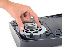
    • Use a T8 Torx Security screwdriver to remove the four screws securing the fan:

    • One 31.7 mm‑long screw

    • Two 21.5 mm‑long screws

    • One 11.5 mm‑long screw

  10. Main Board Removal, Remove the fan: crwdns2935265:010crwdnd2935265:01crwdnd2935265:02crwdne2935265:0 Main Board Removal, Remove the fan: crwdns2935265:010crwdnd2935265:02crwdnd2935265:02crwdne2935265:0
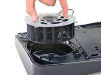
    • Use your fingers to grab the fan by its vents and lift it straight up to remove it.

    • During reassembly:

    • This is a good point to clean the fan. Use a clean cloth and some compressed air to remove any dust or dirt.

    • Insert the fan so its cables are near their connector.
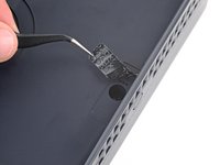
  11. Main Board Removal, Peel up the tamper evident sticker: crwdns2935265:011crwdnd2935265:01crwdnd2935265:02crwdne2935265:0 Main Board Removal, Peel up the tamper evident sticker: crwdns2935265:011crwdnd2935265:02crwdnd2935265:02crwdne2935265:0
  12. Main Board Removal, Remove the fan grille: crwdns2935265:012crwdnd2935265:01crwdnd2935265:03crwdne2935265:0 Main Board Removal, Remove the fan grille: crwdns2935265:012crwdnd2935265:02crwdnd2935265:03crwdne2935265:0 Main Board Removal, Remove the fan grille: crwdns2935265:012crwdnd2935265:03crwdnd2935265:03crwdne2935265:0
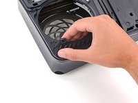
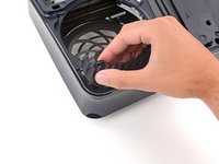
    • Use your fingers to unclip and remove the plastic grille near the fan recess.

  13. Main Board Removal, Remove the right‑side inner shell screws: crwdns2935265:013crwdnd2935265:01crwdnd2935265:02crwdne2935265:0 Main Board Removal, Remove the right‑side inner shell screws: crwdns2935265:013crwdnd2935265:02crwdnd2935265:02crwdne2935265:0
    • Use a T8 Torx Security screwdriver to remove the 10 screws securing the right‑side inner shell:

    • Four 18.8 mm‑long screws

    • Two 18.6 mm‑long screws

    • Four 31.7 mm‑long screws

  14. Main Board Removal, Remove the right‑side inner shell: crwdns2935265:014crwdnd2935265:01crwdnd2935265:02crwdne2935265:0 Main Board Removal, Remove the right‑side inner shell: crwdns2935265:014crwdnd2935265:02crwdnd2935265:02crwdne2935265:0
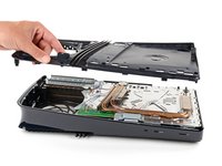
    • Lift the right‑side inner shell straight up and remove it.

  15. Main Board Removal, Disconnect the CMOS board: crwdns2935265:015crwdnd2935265:01crwdnd2935265:03crwdne2935265:0 Main Board Removal, Disconnect the CMOS board: crwdns2935265:015crwdnd2935265:02crwdnd2935265:03crwdne2935265:0 Main Board Removal, Disconnect the CMOS board: crwdns2935265:015crwdnd2935265:03crwdnd2935265:03crwdne2935265:0
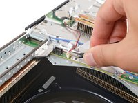
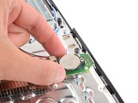
    • Use a pair of angled tweezers to firmly grip the sides of the CMOS board connector, holding the tweezers as close to the connector as possible to get a good grip.

    • Pull the connector straight up and out of its socket to disconnect it.

    • If you're having trouble, try rocking the connector side-to-side to loosen it.

  16. Main Board Removal, Remove the CMOS board: crwdns2935265:016crwdnd2935265:01crwdnd2935265:03crwdne2935265:0 Main Board Removal, Remove the CMOS board: crwdns2935265:016crwdnd2935265:02crwdnd2935265:03crwdne2935265:0 Main Board Removal, Remove the CMOS board: crwdns2935265:016crwdnd2935265:03crwdnd2935265:03crwdne2935265:0
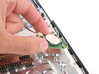
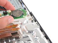
    • Use your fingers to lift the CMOS board off the small metal nubs and pull it toward the center of your console to remove it.

    • If your new board doesn't come with a cable, transfer the original cable to your replacement board.

  17. Main Board Removal, Disconnect the antenna cables: crwdns2935265:017crwdnd2935265:01crwdnd2935265:03crwdne2935265:0 Main Board Removal, Disconnect the antenna cables: crwdns2935265:017crwdnd2935265:02crwdnd2935265:03crwdne2935265:0 Main Board Removal, Disconnect the antenna cables: crwdns2935265:017crwdnd2935265:03crwdnd2935265:03crwdne2935265:0
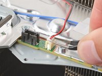
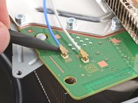
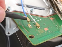
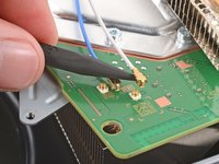
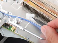
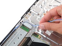
    • Insert a spudger under the metal neck of one of the antenna cable's coaxial connectors and lift straight up to disconnect it.

    • Repeat the process to disconnect the other antenna cable.

    • During reassembly:

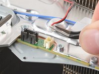
    • Use the markings on the board to reconnect the antenna cables to the correct sockets—connect the blue cable to the socket marked RB and the white cable to the one marked RW.

    • To reconnect a cable, hold the metal connector head over its socket and press down with the flat end of a spudger until the connector snaps into place. Don't try to force the connector into place. If you're having trouble, reposition the connector and try again.

  18. Main Board Removal: crwdns2935265:018crwdnd2935265:01crwdnd2935265:03crwdne2935265:0 Main Board Removal: crwdns2935265:018crwdnd2935265:02crwdnd2935265:03crwdne2935265:0 Main Board Removal: crwdns2935265:018crwdnd2935265:03crwdnd2935265:03crwdne2935265:0
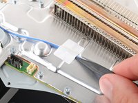
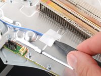
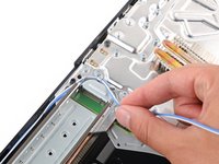
    • Use the point of a spudger to flip up the small piece of white tape securing the antenna cables to the metal shield.

  19. Main Board Removal, Move the antenna cables: crwdns2935265:019crwdnd2935265:01crwdnd2935265:03crwdne2935265:0 Main Board Removal, Move the antenna cables: crwdns2935265:019crwdnd2935265:02crwdnd2935265:03crwdne2935265:0 Main Board Removal, Move the antenna cables: crwdns2935265:019crwdnd2935265:03crwdnd2935265:03crwdne2935265:0
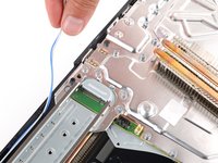
    • Use your fingers to de‑route the antenna cables from their clips on the metal shield.

    • Move the antenna cables over the side of your PlayStation so they're out of the way.

  20. Main Board Removal, Pry up the heat sink: crwdns2935265:020crwdnd2935265:01crwdnd2935265:03crwdne2935265:0 Main Board Removal, Pry up the heat sink: crwdns2935265:020crwdnd2935265:02crwdnd2935265:03crwdne2935265:0 Main Board Removal, Pry up the heat sink: crwdns2935265:020crwdnd2935265:03crwdnd2935265:03crwdne2935265:0
    • Thermal paste bonds the bottom heat sink fins (closest to the power button) to the metal shield. Depending on the age of your device and condition of the thermal paste, separating the heat sink may take some force.

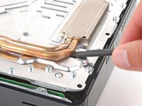
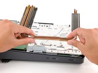
    • Insert the flat end of a spudger under the bend in the copper pipes, near the heat sink's bottom edge.

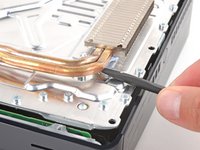
    • Use your spudger to pry up the heat sink, applying steady pressure to separate it from the thermal paste.

    • If the heat sink doesn't fully separate, use your spudger to pry up the bottom edge on the other side of the metal fins.

  21. Main Board Removal, Remove the heat sink: crwdns2935265:021crwdnd2935265:01crwdnd2935265:02crwdne2935265:0 Main Board Removal, Remove the heat sink: crwdns2935265:021crwdnd2935265:02crwdnd2935265:02crwdne2935265:0
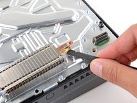
    • Grip the heat sink by its copper pipes and remove it.

    • Don't grip the sharp, metal fins on the heat sink.

    • During reassembly:

    • Before removing any of the old thermal paste, note the location and quantity of thermal paste on the metal shield. This way you'll know how much to use when replacing it.

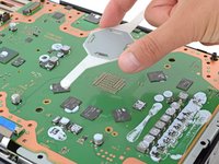
    • Use the flat end of a spudger to scrape up and remove as much of the old thermal paste as possible.

    • Remove all the remaining thermal paste and its residue with high‑concentration (>90%) isopropyl alcohol and a microfiber cloth.

    • Apply new thermal paste where the old paste was.

    • Firmly push the heat sink into place.

  22. Main Board Removal, Remove the metal shield plate screws: crwdns2935265:022crwdnd2935265:01crwdnd2935265:02crwdne2935265:0 Main Board Removal, Remove the metal shield plate screws: crwdns2935265:022crwdnd2935265:02crwdnd2935265:02crwdne2935265:0
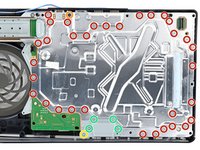
    • Use a T8 Torx Security screwdriver to remove 39 screws:

    • Thirty‑three 7.5 mm‑long screws securing the metal shield plate

    • One 11.5 mm‑long black screw securing the main board assembly

    • One 28.7 mm‑long screw securing the interconnect cable cover

    • Four 7.5 mm‑long screws securing the interconnect cable cover

  23. Main Board Removal, Remove the interconnect cable cover: crwdns2935265:023crwdnd2935265:01crwdnd2935265:02crwdne2935265:0 Main Board Removal, Remove the interconnect cable cover: crwdns2935265:023crwdnd2935265:02crwdnd2935265:02crwdne2935265:0
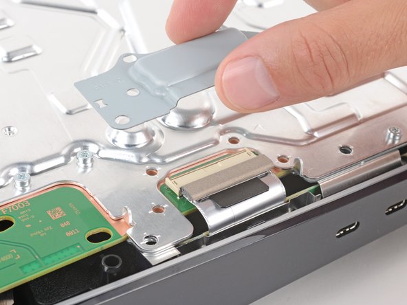
    • Remove the interconnect cable cover.

  24. Main Board Removal, Disconnect the interconnect cable: crwdns2935265:024crwdnd2935265:01crwdnd2935265:03crwdne2935265:0 Main Board Removal, Disconnect the interconnect cable: crwdns2935265:024crwdnd2935265:02crwdnd2935265:03crwdne2935265:0 Main Board Removal, Disconnect the interconnect cable: crwdns2935265:024crwdnd2935265:03crwdnd2935265:03crwdne2935265:0
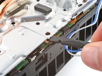
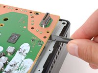
    • Use the flat end of a spudger to push down the metal bar on the interconnect cable socket.

    • With the metal bar held down, use your fingers or tweezers to grip the plastic pull tab and slide the cable straight out of its socket.

    • During reassembly, insert the interconnect cable into the socket until it snaps into place.

  25. Main Board Removal, Separate the top shield plate: crwdns2935265:025crwdnd2935265:01crwdnd2935265:03crwdne2935265:0 Main Board Removal, Separate the top shield plate: crwdns2935265:025crwdnd2935265:02crwdnd2935265:03crwdne2935265:0 Main Board Removal, Separate the top shield plate: crwdns2935265:025crwdnd2935265:03crwdnd2935265:03crwdne2935265:0
    • Thermal pads bond the top shield plate to the main board. Depending on the age of your device and conditions of the pads, it may take significant force to separate the plate.

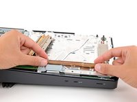
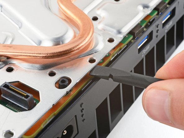
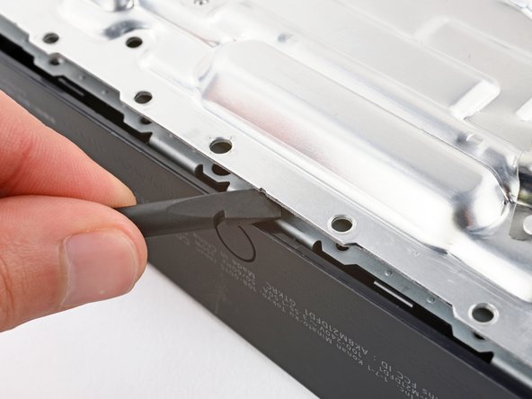
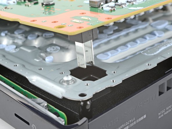
    • Insert the flat end of a spudger between the top shield plate and the main board and pry up to release the plate. Work your way around the perimeter until it separates completely.

  26. Main Board Removal, Remove the top shield plate: crwdns2935265:026crwdnd2935265:01crwdnd2935265:02crwdne2935265:0 Main Board Removal, Remove the top shield plate: crwdns2935265:026crwdnd2935265:02crwdnd2935265:02crwdne2935265:0
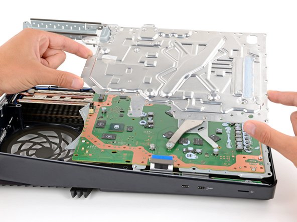
    • Lift and remove the top shield plate.

    • During reassembly, this is a good point to replace any thermal pads on the top of the main board, if necessary. The pads may be stuck to both the top shield plate and the main board.

    • It's important that the replacement pads are the same thickness as the originals, otherwise the foam around the APU may not seal properly.

  27. Main Board Removal, Remove the main board screws: crwdns2935265:027crwdnd2935265:01crwdnd2935265:03crwdne2935265:0 Main Board Removal, Remove the main board screws: crwdns2935265:027crwdnd2935265:02crwdnd2935265:03crwdne2935265:0 Main Board Removal, Remove the main board screws: crwdns2935265:027crwdnd2935265:03crwdnd2935265:03crwdne2935265:0
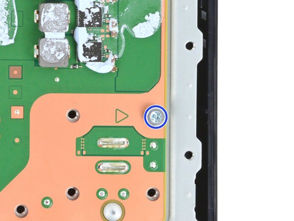
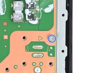
    • Use a T8 Torx Security screwdriver to remove the three remaining screws securing the main board:

    • Two 16.3 mm‑long screws securing the APU tension bracket

    • Don't remove or install one screw at a time, or you may damage the APU. During disassembly and reassembly, alternate between the two screws a half turn at a time to maintain even pressure on the bracket.

    • One 7.5 mm‑long screw

  28. Main Board Removal, Remove the APU brackets: crwdns2935265:028crwdnd2935265:01crwdnd2935265:03crwdne2935265:0 Main Board Removal, Remove the APU brackets: crwdns2935265:028crwdnd2935265:02crwdnd2935265:03crwdne2935265:0 Main Board Removal, Remove the APU brackets: crwdns2935265:028crwdnd2935265:03crwdnd2935265:03crwdne2935265:0
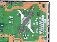
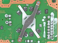
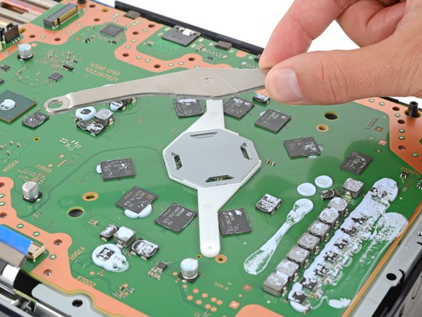
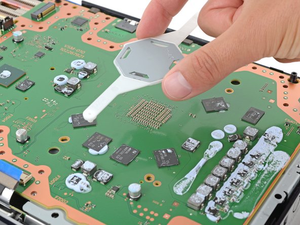
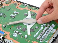
    • Lift and remove both APU brackets from the board.

    • During reassembly:

    • Put the bracket with plastic arms on first so the pegs go into their cutouts.

    • Then, put the metal bracket onto the plastic one so they're perpendicular and the screw holes line up.

  29. Main Board Removal, Begin separating the main board: crwdns2935265:029crwdnd2935265:01crwdnd2935265:03crwdne2935265:0 Main Board Removal, Begin separating the main board: crwdns2935265:029crwdnd2935265:02crwdnd2935265:03crwdne2935265:0 Main Board Removal, Begin separating the main board: crwdns2935265:029crwdnd2935265:03crwdnd2935265:03crwdne2935265:0
    • Don't try to fully remove the motherboard during this step—the corner near the power button is still secured by metal prongs, which will be disconnected in the next step.

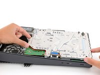
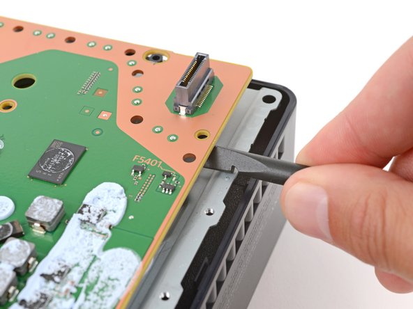
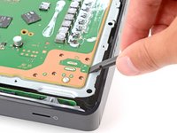
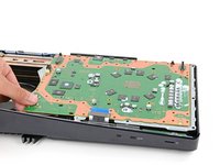
    • Insert the flat end of a spudger under the main board (near the fan recess) and twist the spudger to separate the board.

    • Repeat this process at different points around the perimeter to separate the board.

  30. Main Board Removal, Disconnect the board from the power supply: crwdns2935265:030crwdnd2935265:01crwdnd2935265:03crwdne2935265:0 Main Board Removal, Disconnect the board from the power supply: crwdns2935265:030crwdnd2935265:02crwdnd2935265:03crwdne2935265:0 Main Board Removal, Disconnect the board from the power supply: crwdns2935265:030crwdnd2935265:03crwdnd2935265:03crwdne2935265:0
    • The power supply is connected to the bottom of the main board assembly by metal prongs that plug into the corner near the power button.

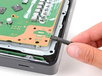
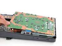
    • Insert the flat end of a spudger between the bottom edge of the board and lower shield plate, by the two parallel solder joints near the corner with the power button.

    • Use your spudger to pry up the board until the two prongs come completely out of their socket.

    • You should feel the prongs slide out.

    • During reassembly, press down on the corner of the board to fully seat the prongs in the power supply—you should feel them slide into place.

  31. Main Board Removal, Remove the main board: crwdns2935265:031crwdnd2935265:01crwdnd2935265:03crwdne2935265:0 Main Board Removal, Remove the main board: crwdns2935265:031crwdnd2935265:02crwdnd2935265:03crwdne2935265:0 Main Board Removal, Remove the main board: crwdns2935265:031crwdnd2935265:03crwdnd2935265:03crwdne2935265:0
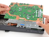
    • Remove the main board, flip it over, and carefully lay it on a clean work surface, so the APU is facing up

    • Don't press the board against your work surface, or you may damage fragile components.

    • During reassembly:

    • Make sure all cables that connect to the board are out of the way so they don't get trapped underneath.

    • Carefully flip the board over so the APU is on the bottom, making sure no liquid metal spills.

    • Keep the board level and lower it into place.

crwdns2935217:0crwdne2935217:0

Spencer Day

crwdns2935283:009/14/22crwdne2935283:0

111.815 crwdns2915208:0crwdne2915208:0

crwdns2935297:0811crwdne2935297:0

crwdns2915084:0crwdne2915084:0

iFixit crwdns2935289:0iFixitcrwdne2935289:0

Staff

crwdns2931471:0120crwdne2931471:0

crwdns2935297:020.002crwdne2935297:0

crwdns2947412:00crwdne2947412:0

crwdns2917038:0crwdne2917038:0

crwdns2936625:0crwdne2936625:0:

crwdns2936751:024crwdne2936751:0 0

crwdns2936753:07crwdne2936753:0 0

crwdns2936753:030crwdne2936753:0 8

crwdns2942667:0crwdne2942667:0 37