crwdns2915892:0crwdne2915892:0
Replacement of the upper case requires removal of most components in your MacBook.
crwdns2942213:0crwdne2942213:0
-
-
Remove the eight 4 mm Phillips screws securing the lower case to the MacBook.
-
-
-
Slightly lift the lower case near the vent opening.
-
Continue running your fingers between the lower and upper cases until the upper case pops off its retaining clips.
-
-
-
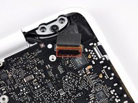
Use the flat end of a spudger to lift the battery connector up out of its socket on the logic board.
-
-
-
Remove the following screws from the optical drive side of the rear vent:
-
Two 10 mm T8 Torx
-
Two 5.2 mm Phillips
-
-
-
Remove the following screws from the port side of rear vent:
-
Two 10 mm T8 Torx
-
Two 5.2 mm Phillips
-
-
-
Carefully lift the rear vent out of the upper case.
-
-
-
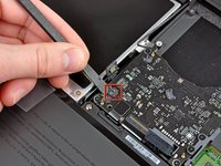
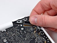
Use the flat end of a spudger to pry the AirPort/Bluetooth ribbon cable up off the logic board.
-
-
-
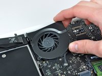
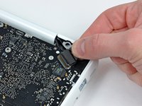
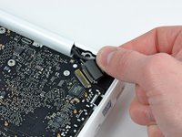
Use a spudger to pry the fan connector straight up and out of its socket on the logic board.
-
-
-
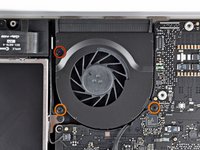
Remove the following three screws securing the fan to the upper case:
-
One 7.1 mm Phillips screw.
-
Two 5 mm Phillips screws.
-
Lift the fan out of the upper case.
-
-
-
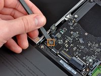
Carefully pry the delicate rear speaker connector up off the logic board. These small L/R speaker connectors are quite easily broken.
-
-
-
Use the flat end of a spudger to pry the optical drive connector up off the logic board.
-
-
-
Use a spudger to pry the right speaker connector and sleep LED connector up off the logic board.
-
-
-
Use the flat end of a spudger to pry the trackpad ribbon cable connector up off the logic board.
-
-
-
Use your fingernail to flip up the locking flap on the ZIF socket for the keyboard ribbon cable.
-
Use the tip of a spudger to slide the keyboard ribbon cable out of its socket.
-
-
-
-
Use the flat end of a spudger to pry the hard drive cable connector up off the logic board.
-
-
-
Use a spudger to pry the left speaker connector and microphone connector up off the logic board.
-
-
-
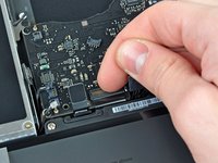
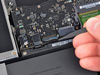
Grab the plastic pull tab secured to the display data cable lock and rotate it toward the DC-In side of the computer.
-
-
-
Gently pull the display data cable connector away from its socket on the logic board.
-
-
-
Remove the six 4.1 to 4.4 mm T6 Torx screws securing the logic board to the upper case.
-
Remove the two 4.1 to 4.5 mm T6 Torx screws securing the MagSafe board to the upper case.
-
On some models, these screws may be T7. Be careful not to strip away the head with a smaller bit.
-
-
-
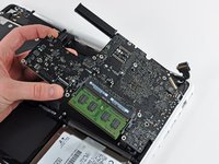
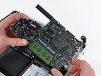
Lift the side of the logic board opposite the ports out of the upper case.
-
Rotate the logic board away from the upper case until the ports clear the lip molded in the upper case.
-
Pull the logic board and MagSafe board away from the edge of the upper case as one piece.
-
-
-
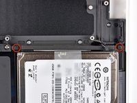
Remove the two Phillips screws securing the hard drive bracket to the upper case.
-
Remove the hard drive bracket from the upper case.
-
-
-
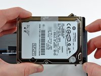
Lift the free side of the hard drive and pull it away from the side of the upper case.
-
-
-
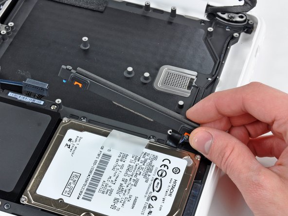
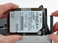
Disconnect the hard drive by pulling the hard drive cable connector away from its socket on the hard drive.
-
-
-
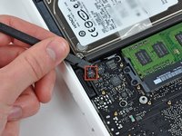
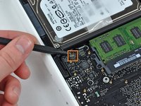
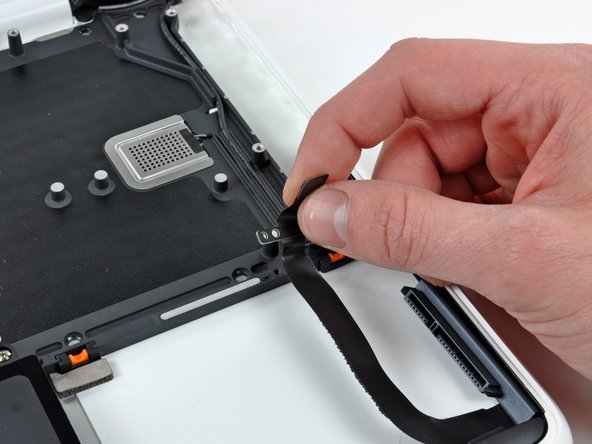
Remove the single 3.1 mm Phillips screw securing the hard drive cable to the upper case.
-
Lift the hard drive cable out of the upper case.
-
-
-
Remove two 5 mm Tri-Wing screws securing the battery to the upper case near the battery connector.
-
-
-
Use the tip of a spudger to carefully peel back the finger of the warning label to reveal a hidden Tri-Wing screw.
-
Remove the 5 mm Tri-Wing screw securing the battery to the upper case.
-
-
-
Remove three 3.1 mm Phillips screws securing the battery near the edge of the upper case.
-
-
-
Lift the battery near its connector and remove it from the upper case.
-
-
-
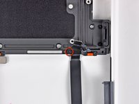
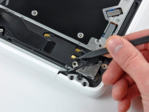
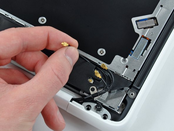
Use the tip of a spudger to pry the AirPort/Bluetooth antenna connectors (three total) up off the AirPort/Bluetooth board.
-
If necessary, de-route the long antenna cable from its slot in the rear speaker housing.
-
-
-
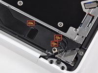
Remove the single 3 mm Phillips screw securing the antenna ground straps to the rear speaker housing.
-
-
-
Remove the single 2.2 mm Phillips screw inserted horizontally into the side of the optical drive.
-
-
-
Remove the single 12 mm Phillips screw securing the rear speaker to the upper case.
-
-
-
Remove the rear speaker assembly from your MacBook.
-
-
-
Remove the single 4.5 mm Phillips screw securing the inner edge of the optical drive to the upper case.
-
-
-
Remove the two 2.5 mm Phillips screws securing the optical drive to the upper case near the optical drive opening.
-
-
-
Lift the optical drive near its connector and pull it away from the upper case to remove it from the computer.
-
-
-
Open your MacBook so the display is perpendicular to the upper case.
-
Place your opened MacBook on a table as pictured.
-
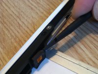
While holding the display and upper case together with your left hand, remove the remaining T8 Torx screw from the lower display bracket.
-
Before retightening the T8 Torx screws, close the display and adjust it so that the back edges of the upper case and display are aligned and the gaps at the ends of the hinge are equal.
-
-
-
Remove the last remaining T8 Torx screw securing the display to the upper case.
-
-
-
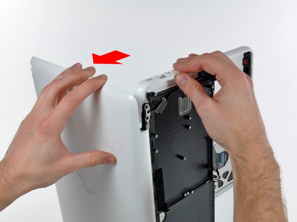
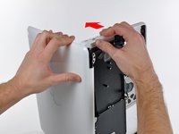
Grab the upper case with your right hand and rotate it slightly toward the top of the display so the upper display bracket clears the edge of the upper case.
-
Rotate the display slightly away from the upper case.
-
-
-
Lift the display up and away from the upper case, minding any brackets or cables that may get caught.
-
-
-
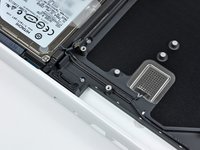
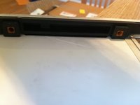
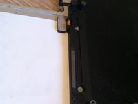
There are four orange and black rubber inserts that the hard drive sits in. One side has full circles and the other side has half circles. (The other side of the half circles are located on the hard drive bracket that was previously removed).
-
The new upper case may not have these inserts. Be sure to remove them from the old and insert into the new.
-
The inserts are easily pried out with a spudger or a flat tipped screwdriver. They are not glued in, but instead have notched sides to hold them in place.
-


To reassemble your device, follow these instructions in reverse order.
To reassemble your device, follow these instructions in reverse order.
crwdns2935221:0crwdne2935221:0
crwdns2935229:012crwdne2935229:0
