crwdns2931315:0crwdnd2931315:0crwdne2931315:0
crwdns2942213:0crwdne2942213:0
-
crwdns2935201:0crwdne2935201:0 crwdns2935203:0crwdne2935203:0
-
With the case closed, place the Unibody top-side down on a flat surface.
-
Depress the grooved side of the access door release latch enough to grab the free end. Lift the release latch until it is vertical.
-
-
crwdns2935201:0crwdne2935201:0 crwdns2935203:0crwdne2935203:0
-
The access door should now be raised enough to lift it up and out of the Unibody.
-
-
crwdns2935201:0crwdne2935201:0 crwdns2935203:0crwdne2935203:0
-
Grab the white plastic tab and pull the battery up and out of the Unibody.
-
-
crwdns2935201:0crwdne2935201:0 crwdns2935203:0crwdne2935203:0
-
Remove the following eight screws securing the lower case to the chassis:
-
One 3 mm Phillips screw.
-
Three 13.5 mm Phillips screws.
-
Four 3.5 mm Phillips screws.
-
-
crwdns2935201:0crwdne2935201:0 crwdns2935203:0crwdne2935203:0
-
Using both hands, lift and remove the lower case off the upper case.
-
-
crwdns2935201:0crwdne2935201:0 crwdns2935203:0crwdne2935203:0
-
Disconnect the camera cable by pulling the male end straight away from its socket.
-
-
crwdns2935201:0crwdne2935201:0 crwdns2935203:0crwdne2935203:0
-
De-route the camera data cable from the channel in the optical drive.
-
-
crwdns2935201:0crwdne2935201:0 crwdns2935203:0crwdne2935203:0
-
Remove the following screws securing the camera data cable and right speaker to the upper case:
-
One 9.9 mm partially threaded Phillips screw
-
One 9.6 mm threaded Phillips screw
-
One 4 mm Phillips screw
-
Slide the camera cable bracket out from under the subwoofer and remove it from the computer.
-
-
crwdns2935201:0crwdne2935201:0 crwdns2935203:0crwdne2935203:0
-
Grab the plastic pull tab secured to the display data cable lock and rotate it toward the DC-in side of the computer.
-
Pull the display data cable connector straight away from its socket.
-
-
crwdns2935201:0crwdne2935201:0 crwdns2935203:0crwdne2935203:0
-
Remove the following two screws from the display data cable bracket:
-
One 7 mm Phillips screw.
-
One 5 mm Phillips screw.
-
Lift the display data cable bracket out of the upper case.
-
-
crwdns2935201:0crwdne2935201:0 crwdns2935203:0crwdne2935203:0
-
Remove the two outer 6 mm Torx screws securing each side of the display to the upper case (4 screws total).
-
-
crwdns2935201:0crwdne2935201:0 crwdns2935203:0crwdne2935203:0
-
Open your MacBook so the display is perpendicular to the upper case.
-
Place your opened MacBook on a table as pictured.
-
While holding the display and upper case together with your left hand, remove the 6 mm Torx screw from the lower display bracket.
-
-
crwdns2935201:0crwdne2935201:0 crwdns2935203:0crwdne2935203:0
-
Remove the last remaining 6 mm Torx screw securing the display to the upper case.
-
-
crwdns2935201:0crwdne2935201:0 crwdns2935203:0crwdne2935203:0
-
Grab the upper case with your right hand and rotate it slightly toward the top of the display so the upper display bracket clears the edge of the upper case.
-
Rotate the display slightly away from the upper case.
-
Lift the display away from the upper case, minding any brackets or cables that may get caught.
-
-
-
crwdns2935201:0crwdne2935201:0 crwdns2935203:0crwdne2935203:0
-
Remove the single Phillips screw securing the hard drive bracket to the chassis.
-
-
crwdns2935201:0crwdne2935201:0 crwdns2935203:0crwdne2935203:0
-
Lift the hard drive by its pull tab enough to grab and remove the retaining bracket.
-
Lift the hard drive out of the chassis, minding the cable attaching it to the computer.
-
-
crwdns2935201:0crwdne2935201:0 crwdns2935203:0crwdne2935203:0
-
Remove the hard drive from its cable by pulling the cable connector straight away from the drive.
-
-
crwdns2935201:0crwdne2935201:0 crwdns2935203:0crwdne2935203:0
-
Remove the four 10.3 mm Phillips screws securing the mid wall to the upper case.
-
-
crwdns2935201:0crwdne2935201:0 crwdns2935203:0crwdne2935203:0
-
Lift the mid wall out of the upper case.
-
-
crwdns2935201:0crwdne2935201:0 crwdns2935203:0crwdne2935203:0
-
Remove the following three screws securing the fan to the upper case:
-
Two 5 mm Phillips screws.
-
One 7 mm Phillips screw.
-
-
crwdns2935201:0crwdne2935201:0 crwdns2935203:0crwdne2935203:0
-
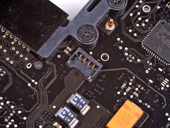
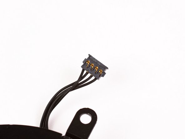
Use a spudger to pry the fan connector straight up and out of its socket on the logic board.
-
-
crwdns2935201:0crwdne2935201:0 crwdns2935203:0crwdne2935203:0
-
Using the flat end of a spudger, pry the subwoofer connector straight up off the logic board.
-
-
crwdns2935201:0crwdne2935201:0 crwdns2935203:0crwdne2935203:0
-
Remove the single Phillips screw securing the subwoofer to the upper case.
-
-
crwdns2935201:0crwdne2935201:0 crwdns2935203:0crwdne2935203:0
-
Lift the subwoofer off the optical drive, and set it above the computer.
-
-
crwdns2935201:0crwdne2935201:0 crwdns2935203:0crwdne2935203:0
-
Use a spudger to pry the optical drive connector straight up off the logic board.
-
-
crwdns2935201:0crwdne2935201:0 crwdns2935203:0crwdne2935203:0
-
Use the flat end of a spudger to pry the hard drive cable connector straight up off the logic board.
-
-
crwdns2935201:0crwdne2935201:0 crwdns2935203:0crwdne2935203:0
-
Remove the three 2.5 mm Phillips screws securing the optical drive to the upper case.
-
-
crwdns2935201:0crwdne2935201:0 crwdns2935203:0crwdne2935203:0
-
Lift the optical drive from its right edge and pull it out of the computer.
-
-
crwdns2935201:0crwdne2935201:0 crwdns2935203:0crwdne2935203:0
-
Peel the hard drive cable from the adhesive securing it to the upper case, and maneuver the plastic retaining block out of the upper case.
-
-
crwdns2935201:0crwdne2935201:0 crwdns2935203:0crwdne2935203:0
-
Peel back the small piece of black tape covering the right speaker cable.
-
Use the tip of a spudger to pry the right speaker up off the adhesive securing it to the upper case.
-
Lift the subwoofer and right speaker assembly out of the upper case.
-
-
crwdns2935201:0crwdne2935201:0 crwdns2935203:0crwdne2935203:0
-
Use the tip of a spudger to flip up the locking lever to release the IR sensor ribbon cable from its socket.
-
Pull the IR sensor ribbon cable straight away from the logic board.
-
-
crwdns2935201:0crwdne2935201:0 crwdns2935203:0crwdne2935203:0
-
Use the flat end of a spudger to pry the trackpad connector straight up off the logic board.
-
-
crwdns2935201:0crwdne2935201:0 crwdns2935203:0crwdne2935203:0
-
Using the tip of a spudger, flip up the keyboard ribbon cable retaining flap.
-
Pull the keyboard ribbon cable straight out of its socket.
-
-
crwdns2935201:0crwdne2935201:0 crwdns2935203:0crwdne2935203:0
-
Remove the two 5 mm Phillips screws securing the keyboard flex bracket to the upper case.
-
Lift the keyboard flex bracket out of the upper case.
-
-
crwdns2935201:0crwdne2935201:0 crwdns2935203:0crwdne2935203:0
-
Remove the single Phillips screw securing the battery cable cover to the upper case.
-
Remove the battery cable cover from the upper case.
-
-
crwdns2935201:0crwdne2935201:0 crwdns2935203:0crwdne2935203:0
-
Use a spudger to pry the battery level indicator cable connector straight up off the logic board.
-
-
crwdns2935201:0crwdne2935201:0 crwdns2935203:0crwdne2935203:0
-
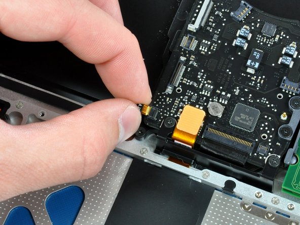
Disconnect the battery cable connector by pulling it straight away from the logic board.
-
-
crwdns2935201:0crwdne2935201:0 crwdns2935203:0crwdne2935203:0
-
Remove the two 4mm Phillips screws securing the bottom case clip to the upper case.
-
Lift the bottom case clip out of the upper case.
-
-
crwdns2935201:0crwdne2935201:0 crwdns2935203:0crwdne2935203:0
-
Use the tip of a spudger to release the microphone from the upper case.
-
-
crwdns2935201:0crwdne2935201:0 crwdns2935203:0crwdne2935203:0
-
Remove the following five screws securing the logic board to the upper case:
-
Four 3 mm Phillips screws.
-
One 3.5 mm Phillips screw.
-
Remove the two 7 mm Phillips screws securing the DC-in board to the upper case.
-
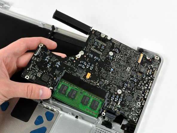
Lift the logic board from its left edge and pull it out of the upper case.
-
-
crwdns2935201:0crwdne2935201:0 crwdns2935203:0crwdne2935203:0
-
Remove the following screws securing the battery connector cover to the upper case:
-
One 2.5 mm Phillips screw.
-
Two 1.5 mm Phillips screws.
-
Lift the battery connector cover out of the upper case.
-
-
crwdns2935201:0crwdne2935201:0 crwdns2935203:0crwdne2935203:0
-
De-route the battery connector cable through the gap in the upper case and remove it from the computer.
-


crwdns2935221:0crwdne2935221:0
crwdns2935229:026crwdne2935229:0

crwdns2917034:0crwdne2917034:0
Having difficulty putting that keyboard ribbon cable back in?
MacBook unibody keyboard ribbon cable won't go in
Put some scotch tape on it and pull up and in.