crwdns2915892:0crwdne2915892:0
The heat sink helps keep the processor cool and happy.
crwdns2942213:0crwdne2942213:0
-
-
With the case closed, place the Unibody top-side down on a flat surface.
-
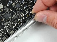
Depress the grooved side of the access door release latch enough to grab the free end. Lift the release latch until it is vertical.
-
-
-
The access door should now be raised enough to lift it up and out of the Unibody.
-
-
-
Grab the white plastic tab and pull the battery up and out of the Unibody.
-
-
-
Remove the following eight screws securing the lower case to the chassis:
-
One 3 mm Phillips screw.
-
Three 13.5 mm Phillips screws.
-
Four 3.5 mm Phillips screws.
-
-
-
Using both hands, lift and remove the lower case off the upper case.
-
-
-
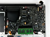
Remove the four 10.3 mm Phillips screws securing the mid wall to the upper case.
-
-
-
Lift the mid wall out of the upper case.
-
-
-
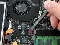
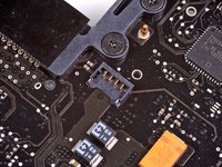
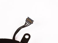
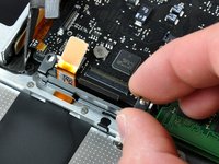
Use a spudger to pry the fan connector straight up off the logic board.
-
-
-
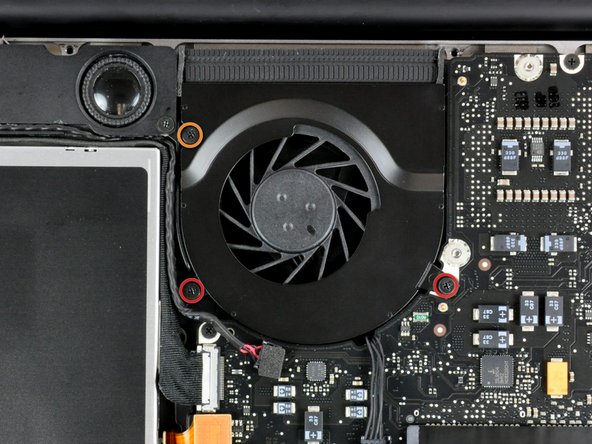
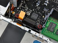
Remove the following three screws securing the fan to the upper case:
-
Two 5 mm Phillips screws.
-
One 7 mm Phillips screw.
-
-
-
-
Each connector is different, so the following steps will show you how disconnect each in detail.
-
-
-
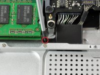
Remove the single Phillips screw securing the battery cable cover to the upper case.
-
Remove the battery cable cover from the upper case.
-
-
-
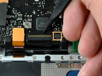
Use a spudger to pry the battery level indicator cable connector straight up off the logic board.
-
-
crwdns2935267:0crwdne2935267:0Tweezers$4.99
-
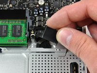
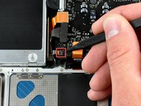
Disconnect the battery cable connector by pulling it straight away from the logic board.
-
-
-
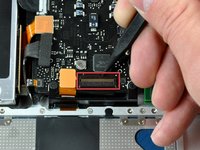
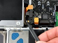
Using the tip of a spudger, flip up the keyboard ribbon cable retaining flap.
-
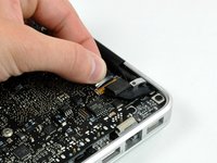
Pull the keyboard ribbon cable straight out of its socket.
-
If the smaller connector at the right side of the keyboard ribbon cable is populated by another small black ribbon cable, remove it in a similar way to the above.
-
-
-
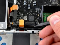
Use the flat end of a spudger to pry the trackpad connector straight up off the logic board.
-
-
-
Use the tip of a spudger to flip up the locking lever to release the IR sensor ribbon cable from its socket.
-
Use the tip of a spudger to pull the IR sensor ribbon cable straight away from the logic board.
-
-
-
Use the flat end of a spudger to pry the hard drive cable connector straight up off the logic board.
-
-
-
Use the flat end of a spudger to pry the optical drive cable connector straight up off the logic board.
-
-
-
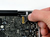
Disconnect the display data cable by pulling the male end straight away from its socket.
-
-
-
Use the flat end of a spudger to pry the subwoofer cable connector straight up off the logic board.
-
-
-
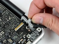
Grab the plastic pull tab secured to the display data cable lock and rotate it toward the DC-in side of the computer.
-
Pull the display data cable connector straight away from its socket.
-
-
-
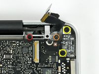
Remove the following two screws securing the display data cable bracket to the upper case:
-
One 7mm Phillips screw.
-
One 5mm Phillips screw.
-
Remove the two 7 mm Phillips screws from the DC-in board.
-
Lift the display data cable bracket out of the upper case.
-
-
-
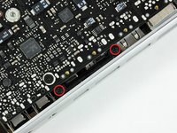
If present, remove the two 4mm Phillips screws securing the bottom case clip to the upper case.
-
Lift the bottom case clip out of the upper case.
-
-
-
Remove the two 5mm Phillips screws securing the keyboard flex bracket to the upper case.
-
Lift the keyboard flex bracket out of the upper case.
-
-
-
Use the tip of a spudger to release the microphone from the upper case.
-
-
-
Remove the following five screws securing the logic board to the upper case:
-
Four 3mm Phillips screws.
-
One 3.5mm Phillips screw.
-
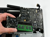
Lift the logic board from its left edge and pull it out of the upper case.
-
-
-
Remove the four 8.5 mm Phillips screws securing the heat sink to the logic board.
-
-
-
Use the flat end of a spudger to pry the thermal sensor connector up off the logic board.
-
-
-
Gently lift the heat sink off the logic board.
-


To reassemble your device, follow these instructions in reverse order.
To reassemble your device, follow these instructions in reverse order.
crwdns2935221:0crwdne2935221:0
crwdns2935229:048crwdne2935229:0

crwdns2947412:06crwdne2947412:0
Great guide! Helped me deep-clean the MacBook and reapply thermal paste to the CPU/GPU. I found it better to do step 15, the keyboard ribbon cable before screwing the keyboard flex bracket back on. The cable is fragile, and it's hard to get back in, so I recommend a fair amount of caution. The same goes for the IR sensor ribbon cable - put it on before you place the logic board down, by turning the logic board to best insert the cable. Also, remember to use the exact correct screwdrivers! If not, you risk stripping the screw heads, which will cause you an extreme amount of frustration later down the line. I completely stripped one of the screws holding down the fan previously, and it took me an hour just to get it off. Other than this, the guide is perfect for all your needs.
Great guide. Laptop was struggling encoding a movie for my iPad. Temps sitting close to 100°c and fan maxed out. After replacing thermal compound and giving the insides a good dust it’s now encoding again but 20-30°c lower and fan isn’t going crazy yet.
Watch out when doing this I did this last night and my mac book stopped charging. When I get home later I will diagnose the issue but if I am correct I just need to re seat the cable.
The guide is missing a vital step: before lifting the logic board, you need to disconnect the cable on the top right underneath.
you mean step 26?