crwdns2915892:0crwdne2915892:0
Use this guide to replace a non-functional microphone.
crwdns2942213:0crwdne2942213:0
-
-
Remove the following ten screws securing the lower case to the upper case:
-
Three 13.5 mm Phillips screws.
-
Seven 3 mm Phillips screws.
-
-
-
Wedge your fingers between the lower case and the vent, and lift upward to release the two clips holding the lower case to the upper case.
-
Remove the lower case.
-
-
-
If present, grab the plastic tab attached to the battery connector and pull it toward the front edge of the device. For Late-2011 models the battery connector will not have a tab and is simply a plug that inserts straight down into the motherboard--to remove pry the plug straight up.
-
-
-
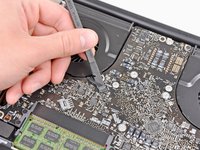
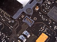
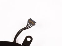
Use the flat end of a spudger to lift the right fan connector out of its socket on the logic board.
-
-
-
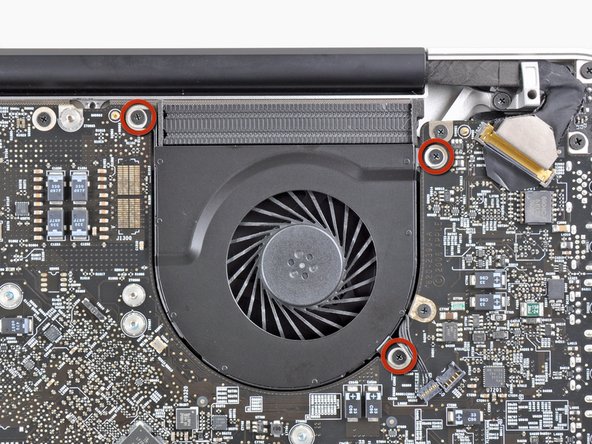
Remove the three 3.1 mm Phillips screws securing the right fan to the logic board.
-
-
-
Remove the right fan from the upper case, minding its cable that may get caught.
-
-
-
Use the flat end of a spudger to lift the left fan connector out of its socket on the logic board.
-
-
-
Remove the three 3.1 mm Phillips screws securing the left fan to the logic board.
-
Remove the left fan from the upper case, minding its cable that may get caught.
-
-
-
Use the tip of a spudger or your fingernail to flip up the retaining flap on the keyboard backlight ribbon cable.
-
Pull the keyboard backlight ribbon cable out of its socket.
-
-
-
-
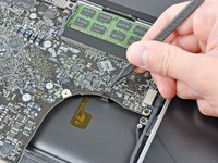
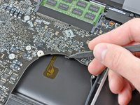
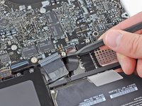
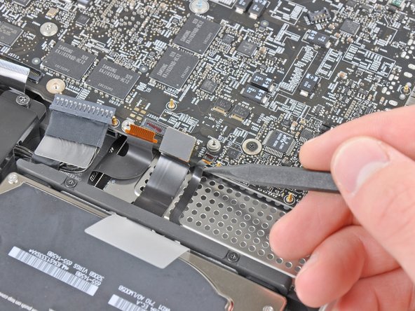
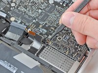
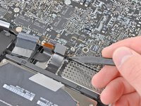
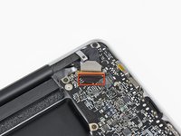
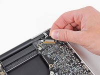
Use the tip of a spudger to push the small plastic cable retainer away from the camera cable socket for enough clearance to remove the camera cable.
-
-
-
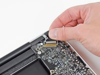
Pull the camera cable toward the optical drive opening to disconnect it from the logic board.
-
-
-
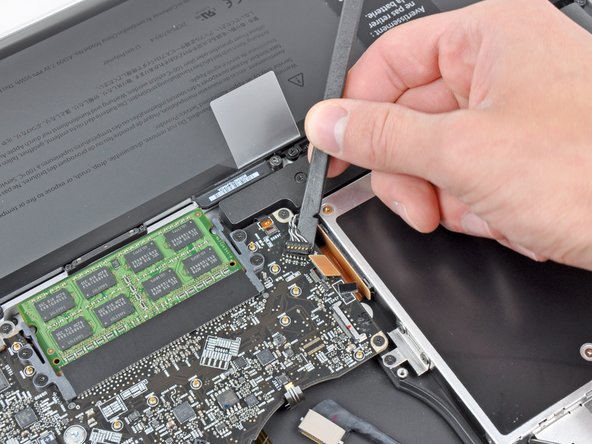
Use the flat end of a spudger to pry the optical drive connector up and out of its socket on the logic board.
-
-
-
Use the flat end of a spudger to lift the subwoofer & right speaker connector out of its socket on the logic board.
-
-
-
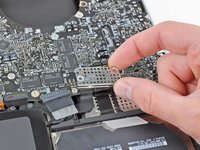
Use the tip of a spudger or your fingernail to flip up the retaining flap on the IR sensor ribbon cable socket.
-
Pull the IR sensor ribbon cable out of its socket.
-
-
-
Remove the following four screws:
-
Two 3.5 mm Phillips screws
-
Two 1.6 mm Phillips screws
-
Remove both connector shields from the logic board.
-
-
-
Use the flat end of a spudger to pry the trackpad connector up and out of its socket on the logic board.
-
-
-
Use your fingernail to flip up the retaining flap on the keyboard ribbon cable socket.
-
Pull the keyboard ribbon cable out of its socket.
-
-
-
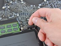
Use your fingernail to flip up the retaining flap on the express card cage ribbon cable socket.
-
Pull the express card cage ribbon cable out of its socket.
-
-
-
Use the flat end of a spudger to lift the hard drive cable connector up and out of its socket on the logic board.
-
-
-
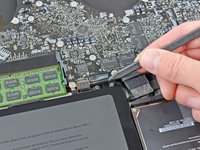
Use the tip of a spudger or your fingernail to flip up the retaining flap on the battery indicator cable socket.
-
Pull the battery indicator ribbon cable out of its socket.
-
-
-
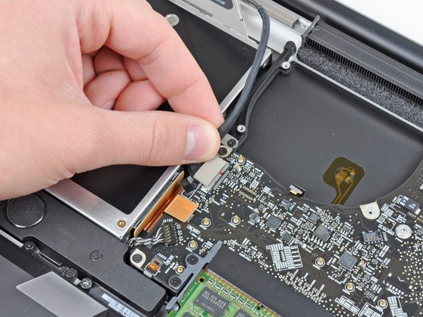
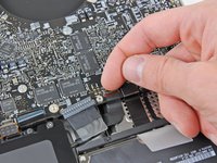
Lift the black plastic flap attached to the display data cable retainer and rotate it toward the DC-In side of the MacBook.
-
Pull the display data cable out of its socket.
-
-
-
Remove the following eight screws securing the logic board and DC-In board to the upper case:
-
Six 3.2 mm Phillips screws
-
Two 7.6 mm Phillips screws
-
-
-
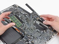
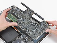
Lift the logic board assembly from the side nearest the optical drive and lift it away from the upper case.
-
Carefully pull the ports and DC-In board away from the side of the upper case and remove the logic board assembly, minding any cables that may get caught.
-
-
-
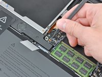
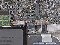
Remove the two 7.9 mm Phillips screws securing the left speaker assembly to the logic board.
-
-
-
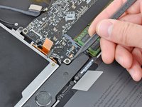
Slightly lift the left speaker assembly off the logic board.
-
Use the flat end of a spudger to lift the microphone and left speaker connectors out of their sockets on the logic board.
-
Remove the left speaker assembly from the logic board.
-
-
-
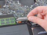
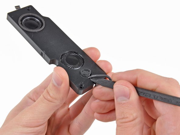
De-route the microphone cable from the channel molded into the left speaker enclosure.
-
Use the tip of a spudger to lift the microphone out of the left speaker enclosure.
-
Microphone remains.
-


To reassemble your device, follow these instructions in reverse order.
To reassemble your device, follow these instructions in reverse order.
crwdns2935221:0crwdne2935221:0
crwdns2935229:04crwdne2935229:0

crwdns2947410:01crwdne2947410:0
We’re going to have to make some changes here. In Step 10 for Late 2011 models, the camera cable looks different, is located in a different place on the logic board, and detaches differently. Yes, there are 5 comments there, but no pictures.