crwdns2915892:0crwdne2915892:0
Use this guide to replace just the LCD rather than the entire display assembly.
crwdns2942213:0crwdne2942213:0
-
-
Use your fingers to push both battery release tabs away from the battery and lift the battery out of the computer.
-
-
-
Remove the four identical Phillips 3.4 mm screws from the memory door. These screws have 4 mm diameter heads rather than the 3 mm heads on the body screws.
-
-
-
Lift the memory door up enough to get a grip on it, and slide it toward you, pulling it away from the casing.
-
-
-
Remove the three Phillips screws in the battery compartment near the latch. Apple was nice enough to tilt these screws at a slight angle to make them easier to remove. On the A1261 these screws have 4 mm diameter heads rather than the 3 mm heads on the body screws.
-
-
-
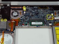
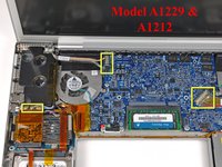
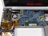
Remove the following six screws:
-
Two 14.5 mm T6 Torx screws on either side of the RAM slot.
-
Four 3.4 mm Phillips screws along the hinge.
-
-
-
Remove the four 3.4 mm Phillips screws on the port side of the computer.
-
-
-
Rotate the computer 90 degrees and remove the two Phillips screws from the rear of the computer.
-
-
-
Rotate the computer 90 degrees again and remove the four Phillips screws from the side of the computer.
-
-
-
Lift up the back of the case and work your fingers along the sides, freeing the case as you go. Once you have freed the sides, you may need to rock the case up and down to free the front of the upper case.
-
-
-
Disconnect the trackpad and keyboard ribbon cable from the logic board.
-
Remove the upper case.
-
-
-
Disconnect the two antenna cables from the AirPort Extreme card, the iSight and inverter cables from the left side of the logic board, and the display data cable from the right side of the logic board. Be careful to slide the connectors as they may become damaged otherwise.
-
Carefully peel the iSight and inverter cables off the top of the left fan and de-route the AirPort antenna cables from the channel in the left speaker.
-
-
-
Remove the ten silver T6 Torx screws securing the display (five on each side-take note that the inside screws on both sides are longer with a thinner head).
-
-
-
-
Grasp the display assembly on both sides and lift it up and out of the computer.
-
-
-
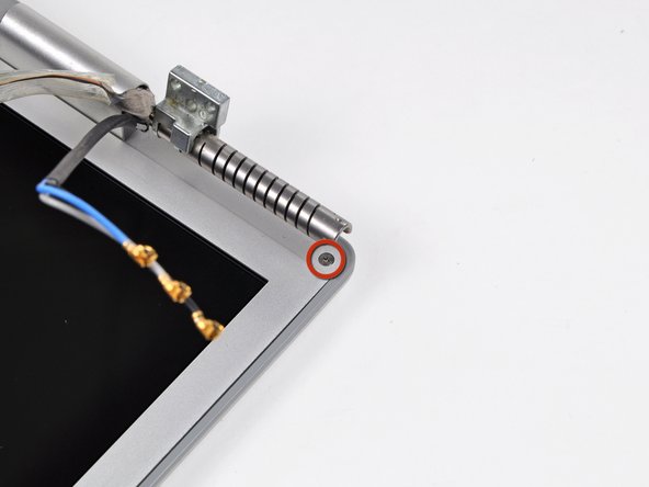
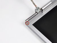
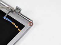
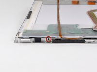
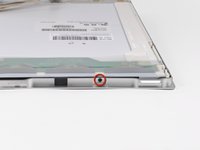
Remove the Phillips screws from the lower left and right corners of the display (two screws total).
-
-
-
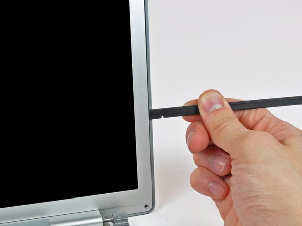
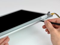
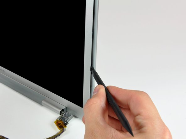
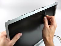
Insert the flat end of a spudger perpendicular to the face of the display between the plastic strip attached to the rear bezel and the front bezel.
-
With the spudger still inserted, rotate it away from the display to separate the front and rear bezels.
-
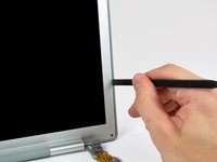
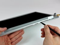
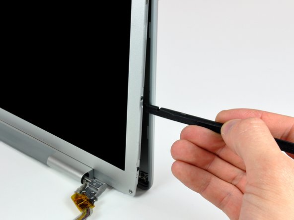
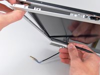
Work along the right edge of the display until the rear bezel is evenly separated from the front bezel.
-
-
-
Insert your spudger between the front and rear display bezels at the lower right corner of the display.
-
Pry the rear bezel away from the front bezel to slightly separate the bottom edge of the rear display bezel.
-
-
-
Insert the flat end of a spudger into the gap between the rear display bezel and the clutch cover.
-
Twist the spudger to separate the lower edge of the rear display bezel from the clutch cover.
-
Work along the lower edge of the rear bezel until it is evenly separated from the clutch cover.
-
-
-
Now that the right and bottom edges of the rear bezel are slightly separated from the front bezel, use a spudger to pop the rear bezel off the tabs near the lower right corner of the display.
-
-
-
Insert the flat end of a spudger between the front bezel and the plastic strip attached to the rear bezel near the screw holes at the bottom corners of the display.
-
Rotate your spudger toward the rear bezel to separate it from the front bezel.
-
-
-
Slightly lift the lower edge of the display and pull it away from the rear display bezel.
-
The rear display bezel remains.
-
-
-
Remove the strip of tape covering the backlight leads.
-
Carefully lift the inverter out of the clutch cover enough to reach the backlight connector.
-
-
-
Disconnect the backlight cable from the inverter board.
-
-
-
Remove the several strips of tape securing the ribbon cables to the LCD.
-
-
-
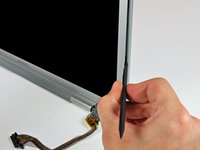
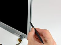
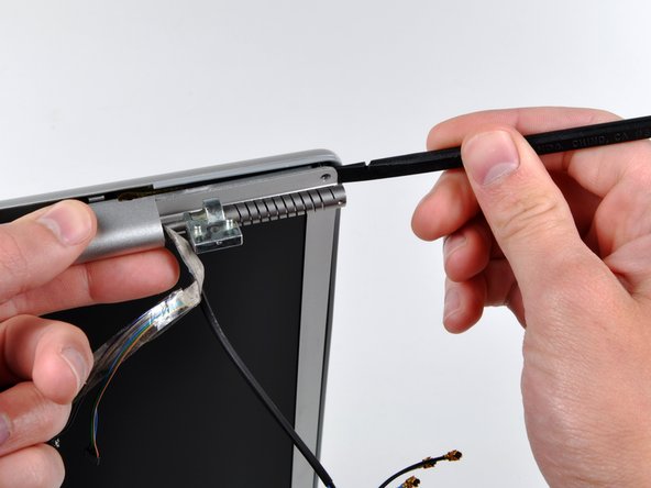
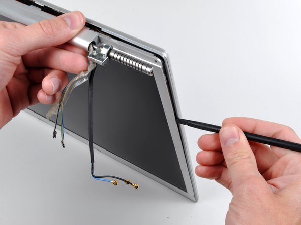
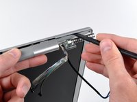
Use the flat end of a spudger to carefully peel the three antenna strips off the lower edge of the LCD.
-
-
-
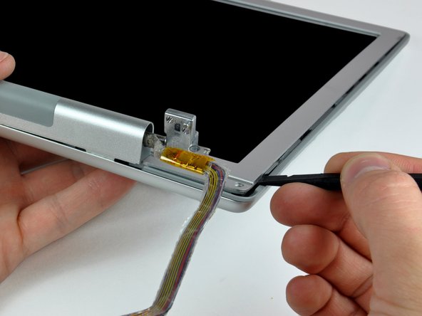
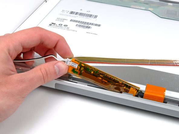
Use the tip of a spudger or your fingernail to flip up the ZIF retaining flap on the camera cable socket at the edge of the camera board near the top center of the front display bezel.
-
Pull the camera cable out of its socket.
-
Peel the camera cable off the foam tape along the top edge of the display.
-
-
-
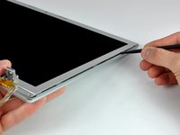
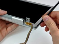
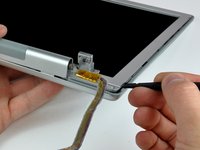
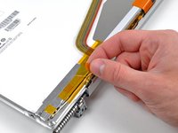
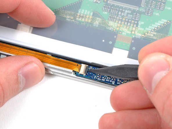
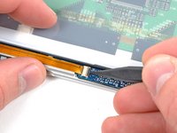
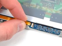
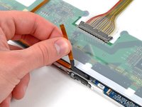
Pull the display data cable toward the bottom edge of the display to disconnect it from the LCD.
-
-
-
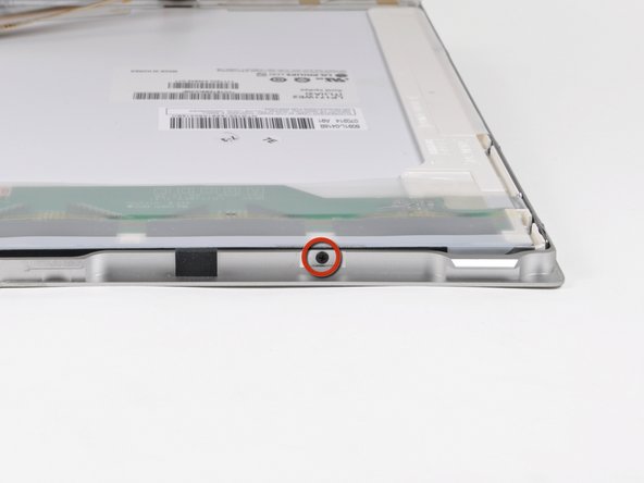
Remove the four 3.2 mm Phillips screws along the right edge of the display.
-
-
-
Remove the two 3.2 mm Phillips screws on the top edge of the display.
-
-
-
Remove the four 3.2 mm Phillips screws along the left edge of the display.
-
-
-
Use the flat end of a spudger to gently lift one of the top corners of the LCD out of the front bezel.
-
-
-
Work your way along the top edge of the LCD, slowly prying the attached steel strip away from the front bezel.
-
Continue prying the LCD off the front bezel along the left side of the display.
-
-
-
Now that the top and left edges are free, slightly lift the LCD out of the front bezel for enough room to pry the steel strip along the lower edge of the LCD away from the front bezel.
-
Pry along the lower edge of the LCD until it is freed from the adhesive on the front bezel.
-
-
-
Lift the LCD out of the front bezel, minding any cables that may get caught.
-
Replacement Note: there are clear plastic spacers attached via adhesive to the sides and bottom of the lcd panel. Be sure to transfer these spacers to the replacement panel for optimum fit.
-


To reassemble your device, follow these instructions in reverse order.
crwdns2935221:0crwdne2935221:0
crwdns2935229:050crwdne2935229:0

crwdns2947412:02crwdne2947412:0
Be sure to reset the PRAM after installation. Otherwise the image may be garbled.
If you don't mind downgrading the resolution from 1680x1050 to 1440x900, you can use another LCD Panel used for 17" Toshiba laptops: LTN170X2-L02. It's almost the same size and spec-wise, except for the lower res...and can be found much cheaper ($50 to $80). The only caveat is that the backlight cable comes out in a slightly different place, and you have to dremel away some of the lid so it doesn't pinch the backlight cable. I was interested to see if the Mac would recognize it, as 1440x900 was not one of the official resolutions mentioned in the original MacBook specs, but it worked!