crwdns2915892:0crwdne2915892:0
Change out the entire display assembly, including the inverter, Airport antennas, hinges and casing.
crwdns2942213:0crwdne2942213:0
-
-
Use your fingers to push both battery release tabs away from the battery and lift the battery out of the computer.
-
-
-
Remove the four identical Phillips 3.4 mm screws from the memory door. These screws have 4 mm diameter heads rather than the 3 mm heads on the body screws.
-
-
-
Lift the memory door up enough to get a grip on it, and slide it toward you, pulling it away from the casing.
-
-
-
Remove the three Phillips screws in the battery compartment near the latch. Apple was nice enough to tilt these screws at a slight angle to make them easier to remove. On the A1261 these screws have 4 mm diameter heads rather than the 3 mm heads on the body screws.
-
-
-
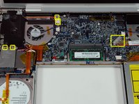
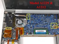
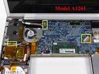
Remove the following six screws:
-
Two 14.5 mm T6 Torx screws on either side of the RAM slot.
-
Four 3.4 mm Phillips screws along the hinge.
-
-
-
-
Remove the four 3.4 mm Phillips screws on the port side of the computer.
-
-
-
Rotate the computer 90 degrees and remove the two Phillips screws from the rear of the computer.
-
-
-
Rotate the computer 90 degrees again and remove the four Phillips screws from the side of the computer.
-
-
-
Lift up the back of the case and work your fingers along the sides, freeing the case as you go. Once you have freed the sides, you may need to rock the case up and down to free the front of the upper case.
-
-
-
Disconnect the trackpad and keyboard ribbon cable from the logic board.
-
Remove the upper case.
-
-
-
Disconnect the two antenna cables from the AirPort Extreme card, the iSight and inverter cables from the left side of the logic board, and the display data cable from the right side of the logic board. Be careful to slide the connectors as they may become damaged otherwise.
-
Carefully peel the iSight and inverter cables off the top of the left fan and de-route the AirPort antenna cables from the channel in the left speaker.
-
-
-
Remove the ten silver T6 Torx screws securing the display (five on each side-take note that the inside screws on both sides are longer with a thinner head).
-
-
-
Grasp the display assembly on both sides and lift it up and out of the computer.
-


To reassemble your device, follow these instructions in reverse order.
crwdns2935221:0crwdne2935221:0
crwdns2935229:046crwdne2935229:0

crwdns2947412:03crwdne2947412:0
Does any one know what the pinout is on the display connector. I am assuming that the first 4 fairly spaced out pins are power. We got a working display form a broken A1229 and are planning to use the display for our experimental purposes. Before doing that we need to know if the display is any good.
thanks
This is my first action with a used Apple laptop A1229. I’m a Vet, Army ‘72-’75 & worked/volunteered about 30 years helping ther Vets and families along with employers match up. My “frustration” as a newbie, is which way to move the pins, up, out, lift, don’t, etc. Would be nice to have close up pics of the ends and see some arrows or descriptors telling me what to do w/o damage. I bumped a short wire that rested w/sensor of some kind on top of MB and detached it, oh well. Trying to get screen to my wife’s laptop, then remove this logic board & hope it works and install into my used A1229 17” Mac Pro. Hoping to save up and purchase a used quad core 17” but time will tell. Thanks to all of you who are putting ut info, helps folks like me.
I hate the screen replacement.