crwdns2915892:0crwdne2915892:0
Use this guide to replace the logic board.
crwdns2942213:0crwdne2942213:0
-
-
Remove the following ten screws securing the lower case to the upper case:
-
Three 13.5 mm (14.1 mm) Phillips screws.
-
Seven 3 mm Phillips screws.
-
-
-
Using both hands, lift the lower case near the vent to pop it off two clips securing it to the upper case.
-
Remove the lower case and set it aside.
-
-
-
Use the edge of a spudger to pry the battery connector upwards from its socket on the logic board.
-
-
-
Bend the battery cable slightly away from its socket on the logic board so it does not accidentally connect itself while you work.
-
-
-
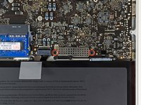
Remove the two 7.4 mm Tri-point screws securing the battery to the upper case.
-
-
-
Carefully peel the battery warning label rounded end (the one without glue) off the upper case between the battery and the optical drive to reveal an additional Tri-point screw.
-
Remove the last 7.4 mm Y0 Tri-point screw securing the battery to the upper case.
-
-
-
Use the attached plastic pull tab to remove the battery from the upper case.
-
Charge it to 100%, and then keep charging it for at least 2 more hours. Next, unplug and use it normally to drain the battery. When you see the low battery warning, save your work, and keep your laptop on until it goes to sleep due to low battery. Wait at least 5 hours, then charge your laptop uninterrupted to 100%.
-
If you notice any unusual behavior or problems after installing your new battery, you may need to reset your MacBook's SMC.
-
-
-
Remove the following three screws securing the left fan to the logic board:
-
Two 3.5 mm T6 Torx screws.
-
One 4.2 mm T6 Torx screw.
-
-
-
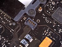
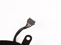
Use the flat end of a spudger to disconnect the left fan connector from the logic board.
-
-
-
Lift the left fan out of the upper case.
-
-
-
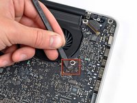
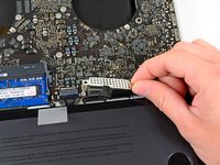
Use the flat end of a spudger to lift the right fan connector out of its socket on the logic board.
-
-
-
-
Remove the three 3.4 mm (3.1 mm) T6 Torx screws securing the right fan to the logic board.
-
Lift the right fan out of its opening in the logic board.
-
-
-
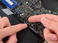
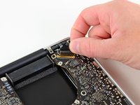
Pull the camera cable out of its socket on the logic board.
-
-
-
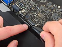
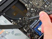
Use the flat end of a spudger to pry the AirPort/Bluetooth connector up from its socket on the logic board.
-
-
-
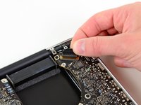
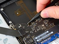
Use the flat end of a spudger to lift the optical drive connector out of its socket on the logic board.
-
-
-
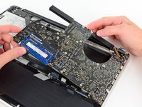
Disconnect the hard drive/IR sensor cable from its socket on the logic board by lifting up from beneath its connector.
-
-
-
Use the flat end of a spudger to lift the subwoofer/right speaker connector out of its socket on the logic board.
-
-
-
Remove the two 1.5 mm ( 1.2 mm ) Phillips screws securing the keyboard/trackpad cable cover to the logic board.
-
Lift the cover off the logic board and set it aside.
-
-
-
Use the flat end of a spudger to pry the trackpad connector up and out of its socket on the logic board.
-
-
-
Use your fingernail to flip up the retaining flap on the keyboard ribbon cable ZIF socket.
-
Use the tip of a spudger to pull the keyboard ribbon cable out of its socket.
-
-
-
Use the flat end of a spudger to lift the battery indicator connector up and out of its socket on the logic board.
-
-
-
Grab the plastic pull tab secured to the display data cable lock and rotate it toward the DC-In side of the computer.
-
Pull the display data cable straight out of its socket on the logic board.
-
-
-
Use the tip of a spudger to flip up the retaining flap on the keyboard backlight ribbon cable ZIF socket.
-
Pull the keyboard backlight ribbon cable out of its socket.
-
-
-
Remove the following nine screws:
-
Seven 3.4 mm ( 3.1 mm) T6 Torx screws on the logic board
-
Two 8 mm T6 Torx screws on the DC-In board
-
-
-
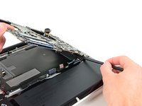
Carefully lift the logic board assembly from its left side and work it out of the upper case, minding the optical drive cable and the I/O ports that may get caught during removal.
-
If necessary, use the flat end of a spudger to separate the microphone from the upper case.
-
Pull the I/O port side of the logic board away from the side of the upper case and remove the logic board assembly.
-
-
-
Remove the six #1 Phillips screws securing the heat sink to the logic board.
-
-
-
Remove the heat sink from the logic board.
-
-
-
Remove the two 5 mm Phillips screws securing the left speaker to the logic board.
-
-
-
Carefully pull the left speaker wires upward to lift the left speaker connector out of its socket on the logic board.
-
-
-
Carefully pull the microphone cables upward to lift the microphone connector out of its socket on the logic board.
-
-
-
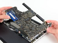
Pull the DC-In board cables toward the heat sink to disconnect the DC-In board from its socket on the logic board.
-
-
-
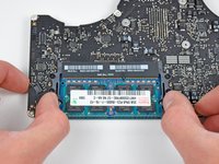
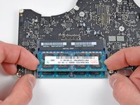
Release the tabs on each side of the RAM chip by simultaneously pushing each tab away from the RAM.
-
After the RAM chip has popped up, pull it straight out of its socket.
-
Logic board remains.
-
If you need to mount the heat sink back onto the logic board, we have a thermal paste guide that makes replacing the thermal compound easy.
-


To reassemble your device, follow these instructions in reverse order.
crwdns2935221:0crwdne2935221:0
crwdns2935229:064crwdne2935229:0

crwdns2947412:010crwdne2947412:0
For step 5 and 6, maybe a reference could be added to a screwdriver for the Tri-wing screws - this seems quite difficult to find (and in the right size...).
Else I agree to what was said before - an excellent guide!
ifixit does it again. Thanks so much for making this resource available. Macbooks are so expensive and its great to be able to fix them and keep em going.
where's a good place to find decent condition logic boards My son was in Afghanistan and there for a long fricking time. While he was gone I had gotten him a MACBOOK Pro 15 loaded anyway It was made in mid-2012 He didn''t even get to use until he was home in 2015 and I hadn't used it. after a couple months he got the froze gray screen with apple logo. Called apple did every single thing possible. Finally they said bring into service center. I did they said would have to go in for repair and wasn't a retina display so I would have to pay . They couldn't tell me exact cost but esitmated at oveer $500.So I googled and I guess it's the graphics which you'd need to replace LB what do you think? Is there another fix? I can do work on windows stuff all the time just never Mac this will be my first. So need good sources if you can help I'd appreciate it. Russ
I have what appears to be a slightly different mainboard from all 15” unibody models. Could anybody help me identify my mainboard and maybe point me to the fuse for the LCD display back light ?
holy moly!!!!! i did it!!!! thank you TEAM iFIXIT!!!!! my mbp15 uni mid-2012 is once again a laptop, once again a computer, once again a tool for my art. Apple Store was going to charge me a lot, more than a replacement logic board, “if they could get one”. since i had done the fan on a 2009, RAM on the 2009 and this machine, and tightened up the screen hinge on this one (i bought it “refurbished”, turns out it has broken battery mounting lugs and was missing a hinge screw), so i figured, wth, lets do this. weeks of hemming and hawing, and i finally ordered the board for ~ $350. spent the morning working on it, forgot to latch the keyboard ZIF, so i had to backtrack, but otherwise, it works. the only thing was that i have to do a whole new backup (Time Machine), in progress now. now iʻm saving money to get a new battery and 1TB SSD, which should be a breeze after doing the logic board. gonna rehab my partnerʻs old white machine (2004?) sometime. one happy and relieved kitty girl here!!!!!