crwdns2942213:0crwdne2942213:0
-
-
Remove the following ten screws securing the lower case to the upper case:
-
Three 13.5 mm (14.1 mm) Phillips screws.
-
Seven 3 mm Phillips screws.
-
-
-
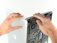
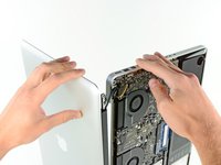
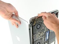
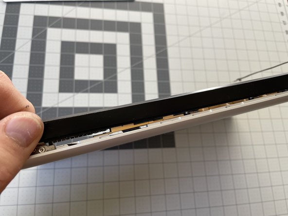
Using both hands, lift the lower case near the vent to pop it off two clips securing it to the upper case.
-
Remove the lower case and set it aside.
-
-
-
Use the edge of a spudger to pry the battery connector upwards from its socket on the logic board.
-
-
-
Bend the battery cable slightly away from its socket on the logic board so it does not accidentally connect itself while you work.
-
-
-
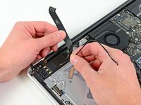
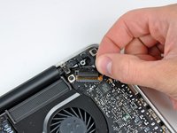
Pull the camera cable connector straight out of its socket on the logic board.
-
-
-
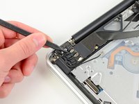
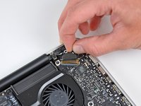
Use the flat end of a spudger to carefully pry the AirPort/Bluetooth ribbon cable up off its socket on the logic board.
-
-
-
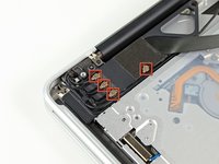
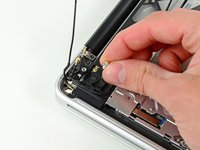
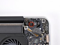
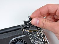
Use the tip of a spudger to pry the four antenna connectors up from their sockets on the AirPort/Bluetooth board.
-
-
-
De-route all four antenna cables from their channels in the AirPort/Bluetooth housing.
-
De-route the camera cable from its channel in the AirPort/Bluetooth housing.
-
-
-
-
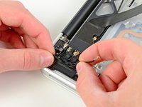
Remove the following two screws securing the AirPort/Bluetooth assembly to the upper case:
-
One 8.6 mm Phillips screw
-
One 3.9 mm Phillips screw
-
-
-
Remove the AirPort/Bluetooth assembly from the upper case, minding any cables that may get caught.
-
-
-
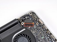
Remove the 8.6 mm Phillips screw securing the antenna/camera cable retainer to the upper case.
-
Remove the antenna/camera cable retainer from the upper case.
-
-
-
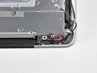
Remove two of the three 6 mm T6 Torx screws securing the right side of the display to the upper case.
-
-
-
Grab the plastic pull tab secured to the display data cable lock and rotate it up and over the connector, toward the DC-In side of the computer.
-
Pull the display data cable straight back (not up) out of its socket on the logic board.
-
-
-
Remove the 8.6 mm Phillips screw securing the display data cable retainer to the upper case.
-
Remove the display data cable retainer from the upper case.
-
-
-
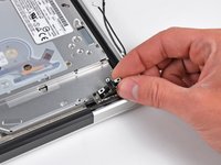
Remove two of the three 6 mm T6 Torx screws securing the left side of the display to the upper case.
-
-
-
Open your MacBook Pro so the display is perpendicular to the upper case.
-
Place your opened MacBook Pro on a table as pictured.
-
While holding the display and upper case together with your left hand, remove the remaining T6 Torx screw from the upper display bracket.
-
-
-
Remove the last remaining T6 Torx screw securing the display to the upper case.
-
-
-
Grab the upper case with your right hand and rotate it slightly toward the top of the display so the upper display bracket clears the edge of the upper case.
-
Rotate the display slightly away from the upper case.
-
Lift the display up and away from the upper case, minding any brackets or cables that may get caught.
-
-
-
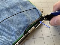
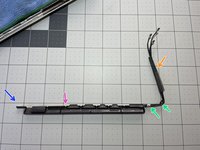
Starting on the right side of the display, slide the antenna's plastic cover approximately 1/4" to the right.
-
Then, lift up the right edge of the plastic cover just enough to separate it from the display.
-
Continue lifting the cover along its length, until the entire cover is separated.
-
Remove the plastic cover and retain for reassembly.
-
-
-
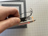
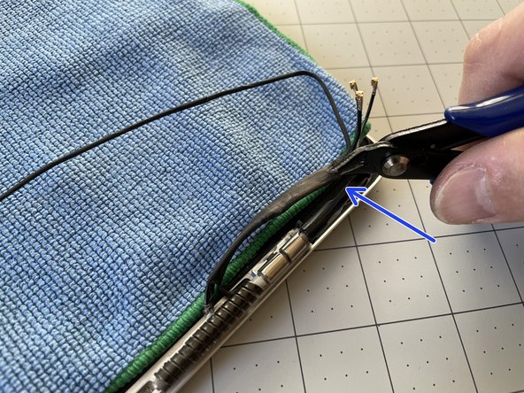
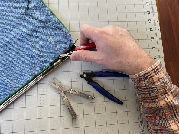
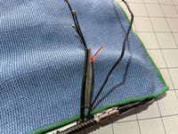
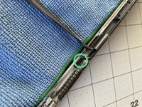
Unwrap the black tape to separate the iSight camera cable from the Airport/Bluetooth cables.
-
If unwrapping is not possible, carefully cut the black tape lengthwise, making sure not to accidentally cut any of the cables -- especially the iSight cable.
-
-
-
Optional: Place a cover on top of your display, just in case your screwdriver slips.
-
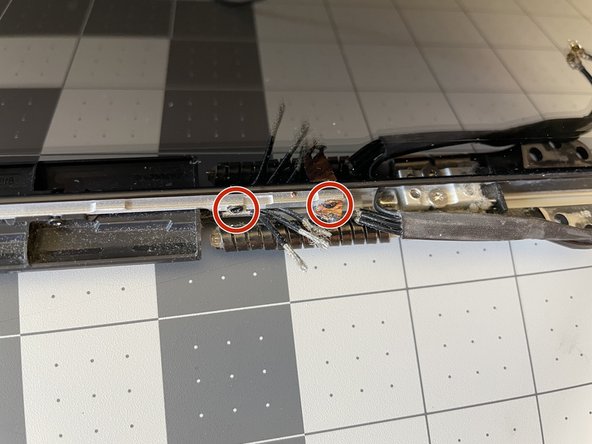
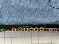
Remove the two #000 Phillips screws on the far-right (see detail photo).
-
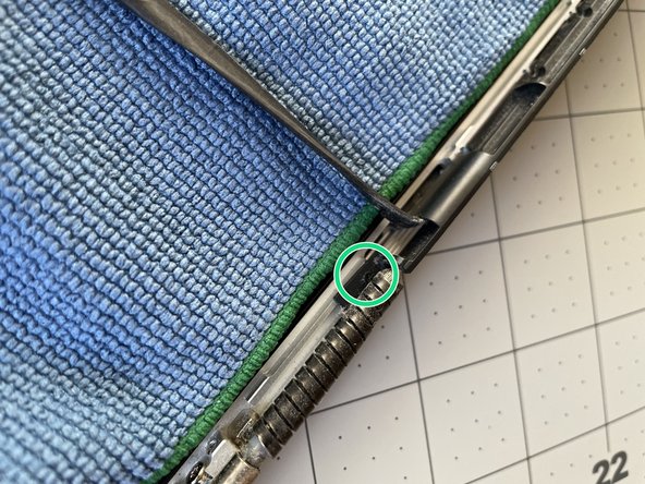
Remove the somewhat-hidden #000 Phillips screw on the far-left of the display (see detail photo).
-
Remove the six #000 Phillips screws in the middle of the antenna board.
-
-
-
Lift up the antenna board up and out of the display.
-
-
-
Make sure to re-wrap the Antenna/iSight cables back with some tape. If your replacement part did not include any, reuse the one you took off. My replacement part came with tape, but I still put a bit of Kapton tape around the black tape to completely close the fold.
-
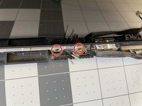
The new antenna hopefully came with the small grounding straps that go around the cables, and get screwed in on the far-right of the display. If they didn't, you'll need to remove them from the old antenna.
-
Insert the replacement board starting with the far-left side. Once inserted, the board should sit loosely in the grooves of the display.
-
When installing the new antenna, first screw in one of the six center screws -- that will help align the far-left screw over its hole.
-


To reassemble your device, follow these instructions in reverse order.
To reassemble your device, follow these instructions in reverse order.
crwdns2935221:0crwdne2935221:0
crwdns2935229:02crwdne2935229:0

crwdns2947410:01crwdne2947410:0
The last steps are pointless, I've followed every single step, and now I'm stuck because I have no idea how to install the piece featured in this guide, with the one we just unmounted. I'm so upset you can't imagine..,.