crwdns2915892:0crwdne2915892:0
Save money by replacing just the LCD rather than the whole display assembly. This guide is not applicable for anti-glare displays.
crwdns2942213:0crwdne2942213:0
-
-
Remove the following ten screws securing the lower case to the upper case:
-
Three 13.5 mm (14.1 mm) Phillips screws.
-
Seven 3 mm Phillips screws.
-
-
-
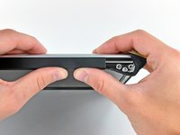
Using both hands, lift the lower case near the vent to pop it off two clips securing it to the upper case.
-
Remove the lower case and set it aside.
-
-
-
Remove the two 7.4 mm Tri-point screws securing the battery to the upper case.
-
Note: For certain repairs (e.g. hard drive), removing the battery is not necessary but it prevents any accidental shorting of electronics on the motherboard. If you do not remove the battery, please be careful as parts of the motherboard might be electrified.
-
-
-
Use the tip of your finger to carefully peel back the corner of the warning label to reveal a hidden Tri-point screw.
-
Remove the last 7.4 mm Tri-point screw securing the battery to the upper case.
-
-
-
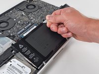
Lift the battery by its plastic pull tab and slide it away from the long edge of the upper case.
-
-
-
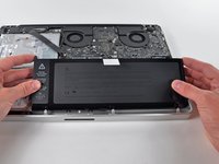
Tilt the battery away from the logic board enough to access the battery cable connector.
-
Pull the battery cable connector away from its socket on the logic board and remove the battery from the upper case.
-
Charge it to 100%, and then keep charging it for at least 2 more hours. Next, unplug and use it normally to drain the battery. When you see the low battery warning, save your work, and keep your laptop on until it goes to sleep due to low battery. Wait at least 5 hours, then charge your laptop uninterrupted to 100%.
-
If you notice any unusual behavior or problems after installing your new battery, you may need to reset your MacBook's SMC.
-
-
-
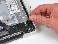
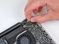
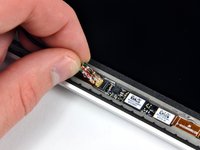
Use the flat end of a spudger to carefully pry the AirPort/Bluetooth ribbon cable up off its socket on the logic board.
-
-
-
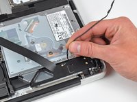
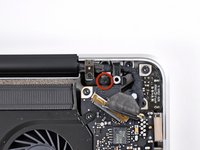
Pull the camera cable connector straight out of its socket on the logic board.
-
-
-
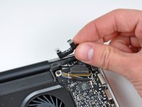
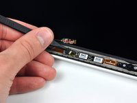
Use the tip of a spudger to pry the three antenna connectors up off the AirPort/Bluetooth board.
-
-
-
De-route all three antenna cables from their channels in the AirPort/Bluetooth housing.
-
De-route the camera cable from its channel in the AirPort/Bluetooth housing.
-
-
-
Remove the following two screws securing the AirPort/Bluetooth housing to the upper case:
-
One 3.8 mm Phillips
-
One 8.6 mm Phillips
-
-
-
Remove the AirPort/Bluetooth assembly from the upper case, minding any cables that may get caught.
-
-
-
-
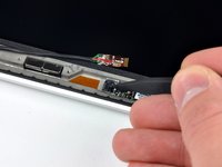
Remove the 8.6 mm Phillips screw securing the antenna/camera cable retainer to the upper case.
-
Remove the antenna/camera cable retainer from the upper case.
-
-
-
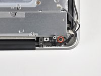
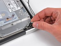
Remove two of the three 6 mm T6 Torx screws securing the right side of the display to the upper case.
-
-
-
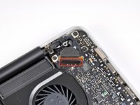
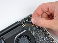
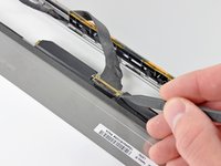
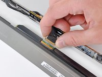
Grab the plastic pull tab secured to the display data cable lock and rotate it toward the DC-In side of the computer.
-
Pull the display data cable straight out of its socket on the logic board.
-
-
-
Remove the 8.6 mm Phillips screw securing the display data cable retainer to the upper case.
-
Remove the display data cable retainer from the upper case.
-
-
-
Remove two of the three 6 mm T6 Torx screws securing the left side of the display to the upper case.
-
-
-
Open your MacBook Pro so the display is perpendicular to the upper case.
-
Place your opened MacBook Pro on a table as pictured.
-
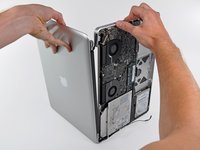
While holding the display and upper case together with your left hand, remove the remaining T6 Torx screw from the upper display bracket.
-
-
-
Remove the last remaining T6 Torx screw securing the display to the upper case.
-
-
-
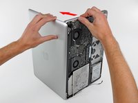
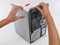
Grab the upper case with your right hand and rotate it slightly toward the top of the display so the upper display bracket clears the edge of the upper case.
-
Rotate the display slightly away from the upper case.
-
Lift the display up and away from the upper case, minding any brackets or cables that may get caught.
-
-
-
Before starting, be sure to clean the display glass with lint-free cloth moistened with a mild solution; it will make the suction cup adhere better, and will make checking for dust on reassembly easier
-
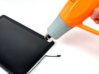
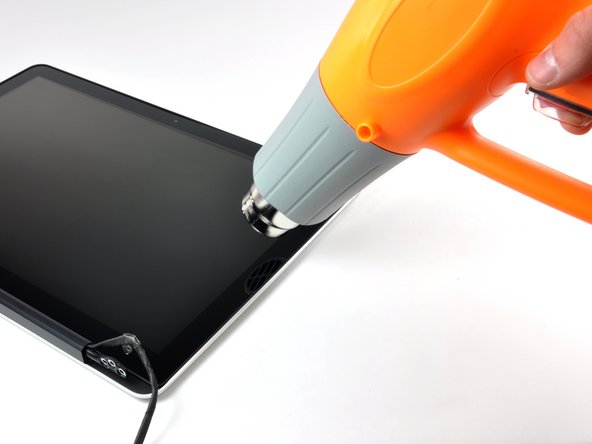
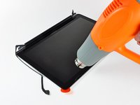
With the heat gun set to low, start by heating the outer black border near the upper right corner of the glass panel.
-
-
crwdns2935267:0crwdne2935267:0Heavy-Duty Suction Cups (Pair)$14.95
-
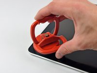
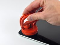
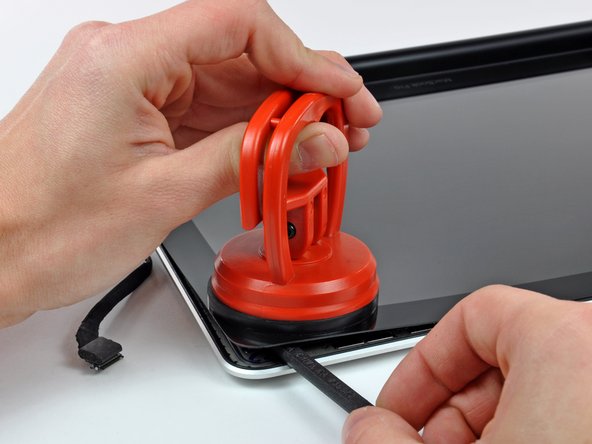
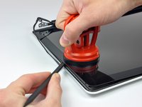
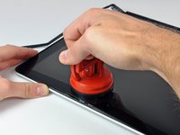
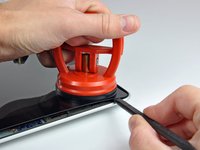
With the panel sufficiently heated, fasten a heavy-duty suction cup near the upper right corner of the display glass.
-
Slowly and gently pull the corner of the display glass up off the display assembly.
-
-
-
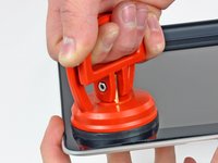
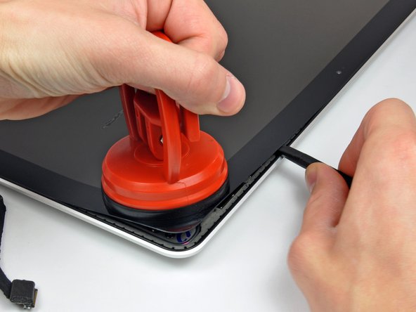
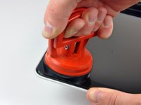
Gently lift the corner of the display glass enough to insert a spudger between it and the display assembly.
-
Use the flat end of a spudger to gently pry up the adhesive securing the front glass to the display.
-
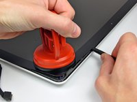
Pry up the glass panel a few inches away from the upper right corner along the top and right edges of the display.
-
-
-
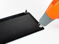
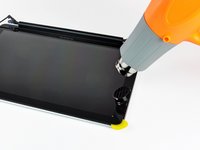
Use a heat gun to soften the adhesive under the black strip along the right side of the front glass panel.
-
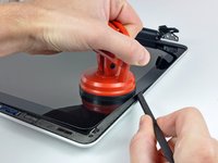
Attach a suction cup along the right side of the front glass panel.
-
Pull up on the glass panel while you use the flat end of a spudger to separate it from the rest of the display assembly.
-
Continue working along the right edge of the front display glass until it is separated from the display.
-
-
-
Use your heat gun to soften the adhesive under the black strip along the top edge of the glass display panel.
-
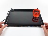
Attach a suction cup near the top edge of the glass display panel and use it to pull the glass panel up off the display.
-
Work along the top edge of the glass panel, carefully using the flat end of a spudger to separate the adhesive if necessary.
-
-
-
Use a heat gun to soften the adhesive under the black strip near the upper left corner of the glass display panel.
-
Attach a suction cup near the upper left corner of the glass display panel.
-
Pull up on the suction cup and use the flat end of a spudger to carefully pry the glass display panel out of the display assembly.
-
-
-
Use a heat gun to soften the adhesive under the black strip along the left side of the front glass panel.
-
Attach a suction cup along the left side of the front glass panel.
-
Pull up on the glass panel while you use the flat end of a spudger to separate it from the rest of the display assembly.
-
Continue working along the left edge of the front display glass until it is separated from the display.
-
-
-
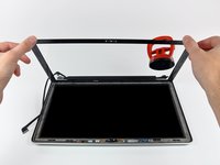
Now that the top, left, and right edges of the glass are free from the display, slowly lift the top edge of the glass panel and gently rotate it out of the display.
-
-
-
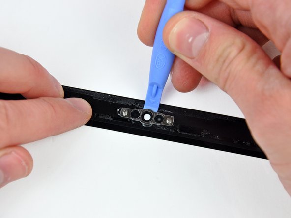
Insert the edge of a plastic opening tool between the display glass and the camera bracket, and run it around the camera bracket to separate it from the display glass.
-
-
-
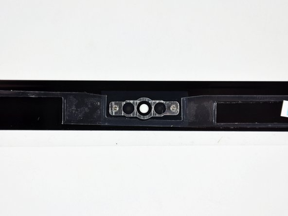
To reconnect the cable, first use the tip of a spudger to remove the piece of foam tape over the camera cable ZIF socket.
-
Use the tip of a spudger to flip up the ZIF cable retainer on the camera cable socket.
-
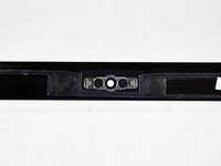
Insert the camera cable into its socket on the camera board and use the tip of a spudger to snap down the ZIF cable retainer, locking the cable in place.
-
-
-
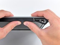
Slide the clutch cover toward the right edge of the display.
-
-
-
Starting at its far left end, rock the clutch cover along its long axis while pulling it away from the clutch hinge.
-
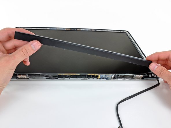
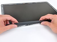
Working from right to left, carefully continue to release and lift the clutch along the lower edge of the display assembly.
-
Lift the clutch cover up off the front bezel and set it aside.
-
-
-
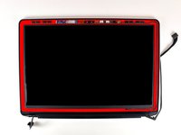
Remove the six 2.9 mm Phillips screws securing the LCD panel to the front bezel.
-
-
-
Pull the LCD toward the top edge of the display to slide the circuitry along its lower edge out of the recess in the aluminum display assembly.
-
-
-
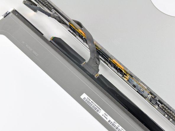
Peel the piece of tape covering the display data cable connector away from the edge closest to the LCD.
-
-
-
Use the tip of a spudger to flip up the thin steel retaining clip securing the display data cable to its socket on the LCD.
-
Pull the display data cable straight away from its socket on the LCD.
-
Lift the LCD out of the display assembly and set it aside.
-


To reassemble your device, follow these instructions in reverse order.
To reassemble your device, follow these instructions in reverse order.
crwdns2935221:0crwdne2935221:0
crwdns2935229:040crwdne2935229:0

crwdns2947412:08crwdne2947412:0
Everything in this guide is simple, except for tearing the glass plate off. I tried with a hairdryer (1200 Watt) first, without success. Then I used a hot air gun (at 400 deg. Celcius, about 750 Fahrenheit). It worked like a charm, but my rubber edge is somewhat shiny, and in one area there's a fingerprint now. Nevertheless, this operation saved me 400 Euros and I'm happy I did it.
I followed the guide and it worked very well. However, after heating the glass for removal I found the lower right corner to be the easiest. Then I used an old credit card to separate the glass from the frame by sliding it around. The hardest part was installing the new LCD panel and glass because of dirt particles and fingerprints. Great tutorial and guide.
For each step in the disassembly process, put the different screws into different shotglasses. Don't leave the screws lying around your desk unless you are a pro.
On a piece of paper, write the step #, and place the shotglass on it. If you have cats who might knock over your shotglasses, label them (the shotglasses, not the cats) using a piece of scotch tape. Then put them where they will not get destroyed by mischievous felines like a roll of toilet paper when you forget to close the bathroom door.
Read all comments in this section; they helped me a lot. DISCLAIMER: I am an idiot, and I confused the shotglasses containing cable restraints. I then spent about an hour trying to figure out where I'd gone wrong before I realized that the restraint in the photo was not the one in my hand. No wonder my father always gives me that look of disappointment when he sees me. Good luck!
Thank you ifixit for making this sound easy. I just shattered my display.
Think you from algeria