crwdns2915892:0crwdne2915892:0
Use this guide to replace a broken left speaker. Replacing the left speaker requires removal of the logic board.
crwdns2942213:0crwdne2942213:0
-
-
Remove the following ten screws securing the lower case to the upper case:
-
Three 13.5 mm (14.1 mm) Phillips screws.
-
Seven 3 mm Phillips screws.
-
-
-
Using both hands, lift the lower case near the vent to pop it off two clips securing it to the upper case.
-
Remove the lower case and set it aside.
-
-
-
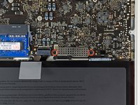
Use the edge of a spudger to pry the battery connector upwards from its socket on the logic board.
-
-
-
Bend the battery cable slightly away from its socket on the logic board so it does not accidentally connect itself while you work.
-
-
-
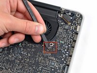
Remove the three 3.4 mm T6 Torx screws securing the left fan to the logic board.
-
-
-
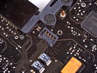
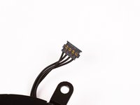
Use the flat end of a spudger to disconnect the left fan connector from the logic board.
-
-
-
Lift the left fan out of the upper case.
-
-
-
Use the flat end of a spudger to lift the right fan connector out of its socket on the logic board.
-
-
-
Remove the three 3.4 mm (3.1 mm) T6 Torx screws securing the right fan to the logic board.
-
Lift the right fan out of its opening in the logic board.
-
-
-
-
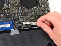
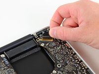
Pull the camera cable out of its socket on the logic board.
-
-
-
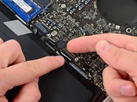
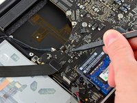
Use the flat end of a spudger to pry the AirPort/Bluetooth connector up from its socket on the logic board.
-
-
-
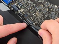
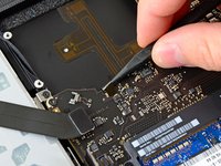
Use the flat end of a spudger to lift the optical drive connector out of its socket on the logic board.
-
-
-
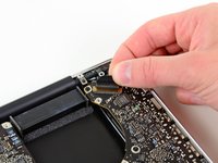
Disconnect the hard drive/IR sensor cable from its socket on the logic board by lifting up from beneath its connector.
-
-
-
Use the flat end of a spudger to lift the subwoofer/right speaker connector out of its socket on the logic board.
-
-
-
Remove the two 1.5 mm ( 1.2 mm ) Phillips screws securing the keyboard/trackpad cable cover to the logic board.
-
Lift the cover off the logic board and set it aside.
-
-
-
Use the flat end of a spudger to pry the trackpad connector up and out of its socket on the logic board.
-
-
-
Use your fingernail to flip up the retaining flap on the keyboard ribbon cable ZIF socket.
-
Use the tip of a spudger to pull the keyboard ribbon cable out of its socket.
-
-
-
Use the flat end of a spudger to lift the battery indicator connector up and out of its socket on the logic board.
-
-
-
Grab the plastic pull tab secured to the display data cable lock and rotate it toward the DC-In side of the computer.
-
Pull the display data cable straight out of its socket on the logic board.
-
-
-
Use the tip of a spudger to flip up the retaining flap on the keyboard backlight ribbon cable ZIF socket.
-
Pull the keyboard backlight ribbon cable out of its socket.
-
-
-
Remove the following nine screws:
-
Seven 3.4 mm ( 3.1 mm) T6 Torx screws on the logic board
-
Two 8 mm T6 Torx screws on the DC-In board
-
-
-
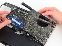
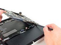
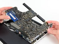
Carefully lift the logic board assembly from its left side and work it out of the upper case, minding the optical drive cable and the I/O ports that may get caught during removal.
-
If necessary, use the flat end of a spudger to separate the microphone from the upper case.
-
Pull the I/O port side of the logic board away from the side of the upper case and remove the logic board assembly.
-
-
-
Remove the two 5 mm Phillips screws securing the left speaker to the logic board.
-
-
-
Carefully pull the left speaker wires upward to lift the left speaker connector out of its socket on the logic board.
-


To reassemble your device, follow these instructions in reverse order.
To reassemble your device, follow these instructions in reverse order.
crwdns2935221:0crwdne2935221:0
crwdns2935229:06crwdne2935229:0

crwdns2947410:01crwdne2947410:0
When putting the logic board back in place, I recommend placing the DC-in board first and screwing it in loosely. Then, begin lowering the motherboard, slowly lifting the cables up and out of the way as you do so, working from the outer edge, in. Once finished, replace the remaining screws, and tighten down the DC-in board screws.
Also, step #15 absolutely requires the use of a #000 Phillips screwdriver, which also works on all of the other Phillips head screws involved in the install. A #00 Phillips head screwdriver is too large.