crwdns2915892:0crwdne2915892:0
Replacing the heat sink requires removal of the logic board and application of new thermal paste.
crwdns2942213:0crwdne2942213:0
-
-
Remove the following ten screws securing the lower case to the upper case:
-
Three 13.5 mm (14.1 mm) Phillips screws.
-
Seven 3 mm Phillips screws.
-
-
-
Using both hands, lift the lower case near the vent to pop it off two clips securing it to the upper case.
-
Remove the lower case and set it aside.
-
-
-
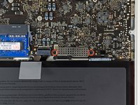
Use the edge of a spudger to pry the battery connector upwards from its socket on the logic board.
-
-
-
Bend the battery cable slightly away from its socket on the logic board so it does not accidentally connect itself while you work.
-
-
-
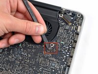
Remove the three 3.4 mm T6 Torx screws securing the left fan to the logic board.
-
-
-
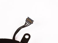
Use the flat end of a spudger to disconnect the left fan connector from the logic board.
-
-
-
Lift the left fan out of the upper case.
-
-
-
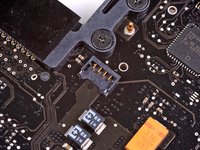
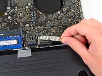
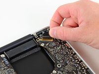
Use the flat end of a spudger to lift the right fan connector out of its socket on the logic board.
-
-
-
-
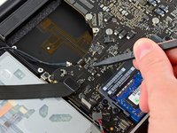
Remove the three 3.4 mm (3.1 mm) T6 Torx screws securing the right fan to the logic board.
-
Lift the right fan out of its opening in the logic board.
-
-
-
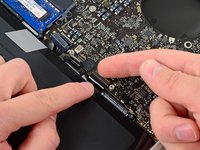
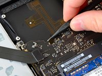
Pull the camera cable out of its socket on the logic board.
-
-
-
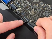
Use the flat end of a spudger to pry the AirPort/Bluetooth connector up from its socket on the logic board.
-
-
-
Use the flat end of a spudger to lift the optical drive connector out of its socket on the logic board.
-
-
-
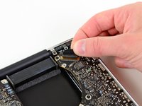
Disconnect the hard drive/IR sensor cable from its socket on the logic board by lifting up from beneath its connector.
-
-
-
Use the flat end of a spudger to lift the subwoofer/right speaker connector out of its socket on the logic board.
-
-
-
Remove the two 1.5 mm ( 1.2 mm ) Phillips screws securing the keyboard/trackpad cable cover to the logic board.
-
Lift the cover off the logic board and set it aside.
-
-
-
Use the flat end of a spudger to pry the trackpad connector up and out of its socket on the logic board.
-
-
-
Use your fingernail to flip up the retaining flap on the keyboard ribbon cable ZIF socket.
-
Use the tip of a spudger to pull the keyboard ribbon cable out of its socket.
-
-
-
Use the flat end of a spudger to lift the battery indicator connector up and out of its socket on the logic board.
-
-
-
Grab the plastic pull tab secured to the display data cable lock and rotate it toward the DC-In side of the computer.
-
Pull the display data cable straight out of its socket on the logic board.
-
-
-
Use the tip of a spudger to flip up the retaining flap on the keyboard backlight ribbon cable ZIF socket.
-
Pull the keyboard backlight ribbon cable out of its socket.
-
-
-
Remove the following nine screws:
-
Seven 3.4 mm ( 3.1 mm) T6 Torx screws on the logic board
-
Two 8 mm T6 Torx screws on the DC-In board
-
-
-
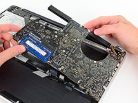
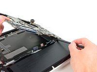
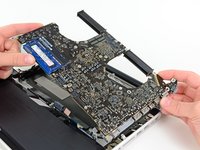
Carefully lift the logic board assembly from its left side and work it out of the upper case, minding the optical drive cable and the I/O ports that may get caught during removal.
-
If necessary, use the flat end of a spudger to separate the microphone from the upper case.
-
Pull the I/O port side of the logic board away from the side of the upper case and remove the logic board assembly.
-
-
-
Remove the six #1 Phillips screws securing the heat sink to the logic board.
-
-
-
Remove the heat sink from the logic board.
-


To reassemble your device, follow these instructions in reverse order.
To reassemble your device, follow these instructions in reverse order.
crwdns2935221:0crwdne2935221:0
crwdns2935229:028crwdne2935229:0

crwdns2947412:03crwdne2947412:0
I followed this guide to replace the thermal paste and clean dust from the heat sinks. That reduced my idle CPU temperature by about 12 degrees Celsius. My cinebench r15 CPU score increased from ~350 to ~450 after waiting the thermal paste break in period. Most noticeably, after replacing the thermal paste and removing dust in the heat sinks, my computer runs much quieter under load. Chrome doesn't make my fans spin up any more!
When I opened the heat sink off the cpu and gpu, it was obvious it needs replacing. So much old dried crusty paste. And I'm too not sure they did a good job with the paste when manufactured.
Done on a ~6.5 year old MacBook Pro 15” late 2011 with the 2670qm CPU (the base model). I used MX-4 thermal paste, which did great on a Tom's hardware thermal paste benchmark. I intend to keep this laptop as long as I can :)
Good luck on your repair and go slowly! Read the comments for each step to avoid ruining your logic board!
Great tutorial, thanks! Wherever it said “use your spudger to…“ I just used my fingernails :D No issues.
Comments are useful too, some additional cautions there.
I followed the instructions and successfully cleaned and reapplied Arctic MX-4 thermal paste on my 2011 15-inch Macbook Pro (2.2 i7/6550M). I had a little trouble removing the logic board as there is some glue holding the speaker on the top of the logic board to the top casing (next to the ethernet port). There was a forum post on this website which was critical for me in knowing how to use a spludger to carefully pry the glued components.
The existing thermal paste actually didn’t look bad, and it was still liquid/paste, not dried (except around the edges where it squeezed out on the edges. It probably wasn’t necessary to perform this maintenance, but there was no way to know that until I pulled this ~10 year-old machine apart. I used the proper tools, including plastic no-marr spludgers and proper torx precision screwdrivers just like the iFixIt specified. I would not recommend even considering this undertaking without the proper tools, patience, and plenty of time available to take your time.
Thx iFixit!