crwdns2915892:0crwdne2915892:0
The ins and outs of replacing your upper case.
crwdns2942213:0crwdne2942213:0
-
-
With the case closed, place the Unibody top-side down on a flat surface.
-
Depress the grooved side of the access door release latch enough to grab the free end. Lift the release latch until it is vertical.
-
-
-
The access door should now be raised enough to lift it up and out of the Unibody.
-
-
-
Grab the translucent plastic tab and pull the battery up and out of the Unibody.
-
If the latch is depressed it will lock the battery in place.
Do I need to wait for the battery to charge completely before using the computer (while plugged in)?
No. You do not need to charge it completely before removing it.
-
-
-
Remove the following eight screws securing the lower case to the chassis:
-
One 5.4 mm Phillips screw.
-
Three 14 mm Phillips screws.
-
Four 3.5 mm Phillips screws.
Hi, My name is Jess I need help asap I accidentally dropped my macbook Pro and i cant find the silver screw for the top left back side, Does any one know if I can replace it with an eye glass screw?? If you can help at all Please e-mail me at Chambliss_jess@yahoo.com thx please help me my bf is going off... ;(
The fixit PH00 is the wrong screw driver for this entire job. It did not fit in the screws, it was too pointy and caused screws to be rounded off.
-
-
-
Using both hands, lift and remove the lower case off the upper case.
About midway along each edge is a snap. To release each snap, gently slide the flat edge of a Spudger under the lower case, then lift the lower case away.
-
-
-
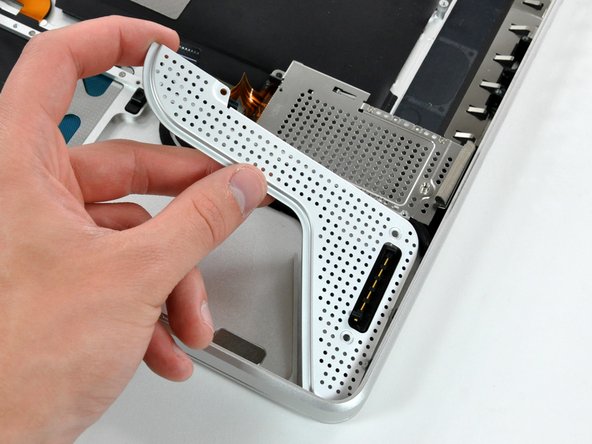
Remove the following 5 screws securing the mid wall to the upper case:
-
Three 10.5 mm Phillips screws.
-
Two 3.7 mm Phillips screws.
-
-
-
Lift the mid wall out of the upper case.
-
-
-
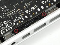
Remove the following six screws securing both the right fan and the left fan to the logic board:
-
Four 3.5 mm Phillips screws.
-
Two 3.2 mm Phillips screws.
Pry under the side where the wires connect.
I think this the screw dimensions may be reversed. My late 2008 Unibody had four 3.2mm and two 3.5mm.
-
-
-
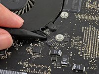
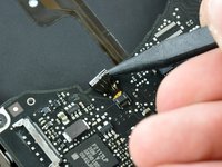
Use the tip of a spudger to lift the right fan connector straight up from its socket on the logic board.
-
Remove the right fan from the case.
Be really gentle and patient with this connector, I popped the socket right off of the logic board (thankfully the already broken one that I was replacing). It actually shouldn't take much force, and just gently work on it until it comes out.
-
-
-
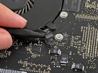
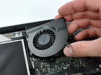
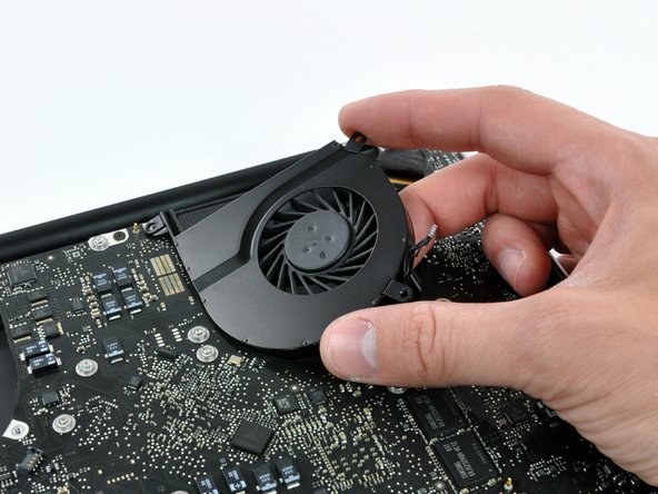
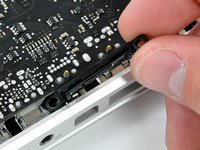
Use the tip of a spudger to lift the left fan connector straight up from its socket on the logic board.
-
Remove the left fan from the case.
I unfortunately broke the fan receptacle connector (2 pin) on the board. How do I order a new connector and how do I put it on?
-
-
-
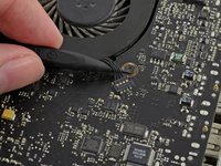
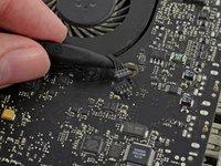
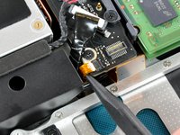
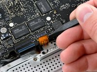
Remove any adhesive from the camera cable connector.
-
Disconnect the camera cable by pulling the male end out of its socket, parallel to the logic board, do not lift it upwards.
There's a little shiny piece of plastic holding this item in place to keep it from sliding out of it's slot. It's glued on and if you don't take it off first, you'll likely bend the connector so that it won't work anymore. Ruined a motherboard because this step was missing.
What this guy said - REMOVE the shiny plastic block first. Also the "straight away" means sliding outwards TOWARDS THE OPTICAL BAY - *NOT* upwards.
I broke the connector for the subwoofer. Do I have to replace the logic board?
It is not necessary to disconnect the camera cable to remove/replace the left speaker. You can leave the cable connected to save you from damaging it.
-
-
-
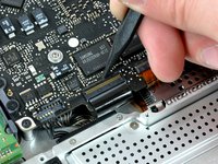
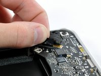
Use a spudger to carefully pry the optical drive connector straight up off its socket on the logic board.
-
-
-
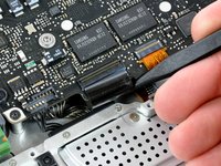
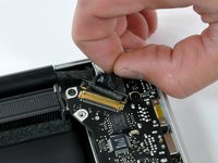
Using the flat end of a spudger, pry the subwoofer connector straight up off its socket on the logic board.
I Broke the subwoofer socket on the logic board. Can I use without subwoofer, or do I now have to replace the logic board?
Sorry to hear this. Yes, you can use the machine without the subwoofer. To be safe, cover the subwoofer plug with some electrical tape so that it can't cause a short circuit somewhere.
-
-
-
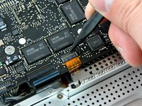
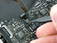
Use the flat end of a spudger to pry the silver-colored hard drive cable connector straight up out of its socket on the logic board.
-
-
-
Use a spudger to pry the trackpad connector straight up out of its socket on the logic board.
-
-
-
-
Using the tip of a spudger, flip up the IR/sleep LED ribbon cable retaining flap.
-
Pull the IR/sleep LED ribbon cable straight out of its socket.
Hi, thanks for this tutorial: it solved my problem.
But unfortunately I have broken the IR/sleep LED ribbon cable socket on motherboard (cable is ok, socket crumbled): computer works fine but now it doesn't go on standby anymore. Is there a way to fix the cable on motherboard (for example with Kapton tape) or is there a software to manage computer standby?
Thanks in advance for your help.
Mary
Hi, thanks for this tutorial, it is really helpful. Unfortunately I cannot push the ribbon cable into the socket. The space is really limited, the cable is hard, and the socket seems to be too narrow. Is there any tool to push this kind of cable in a short space? Very fine plastic tweezers could work? Even without this cable the Mac can work, so I leave it before I break it.
Hideyuki
-
-
-
Use a spudger to pry the battery indicator light connector straight up out of its socket on the logic board.
-
-
-
Using the tip of a spudger, flip up the keyboard ribbon cable retaining flap.
-
Pull the keyboard ribbon cable straight out of its socket.
I ran into trouble when re-installing the keyboard cable. I got everything put back together, plugged it in, and pressed Power... and nothing happened. I took everything apart again, reseated the heat sink and everything, put it back together... and the Power button didn't respond.
The MagSafe light came on, and the battery charge lights came on. But it wouldn't power up.
Finally I figured out that the keyboard cable is really tricky to get in correctly. If you can slide it out with the retaining clip locked (applying very little pressure), then the cable isn't actually in correctly. I had to really fiddle with it, and maybe slide it in one side first, to see that it actually needed to slide in another 1/8th inch or so beyond what felt like "in" the first few times I did it.
Once I'd secured that cable, my MacBook turned on again without a problem. So far, after just replacing the Thermal Paste (I didn't actually install a new heat sink), the computer is running 20°F cooler than it has in years. Thanks!
I think I broke the keyboard ribbon cable, now I have to replace the keyboard.....
I agree. The instructions should place emphasis on seeing how deep this ribbon is. Most ribbons are pretty easy to slot back in. This one is not (maybe because of the colour). The IR/sleep is a b... too!
Hi Jerome. Thank you for your feedback. I agree with you and simolinic. There should be a reminder bullet that warns people about the depth of the ribbon cable. Thanks for adding that. Much appreciated.
Thank you simonlinic, for pointing this out. I was so disapppointed when the MacBook Pro wouldn't start up. I reopened the MacBook and was able to insert the keyboard ribbon cable quite a bit more by pushing agains the top of the cable while inserting it. I tired starting up after that and it still wouldn't start. I took a 15 minute break and then it started up perfectly! I'm grateful to you all!
Here is the best way to reinsert this cable: MacBook unibody keyboard ribbon cable won't go in Putting a piece of tape on the connector (creating a pull-tab) and pulling it in works great.
-
-
-
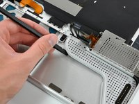
Using the tip of a spudger, flip up the express card cage ribbon cable retaining flap.
-
Pull the express card cage ribbon cable straight out of its socket.
-
-
-
Using the flat end of a spudger, pry the microphone cable connector straight up out of its socket on the logic board.
I don't believe this step is actually necessary, the cable is attached on the other side of the logic board and comes along with it, so it just isn't really necessary to disconnect (although it's not hard either).
-
-
-
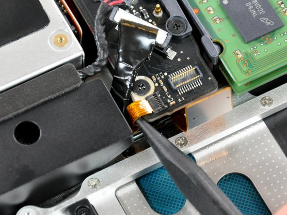
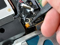
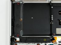
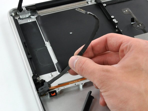
Grab the plastic pull tab secured to the display data cable lock and rotate it toward the DC-in side of the computer.
-
Pull the display data cable connector straight away from its socket.
-
-
-
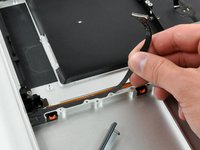
Locate the keyboard backlight ribbon cable (near the left fan space).
-
Using the tip of a spudger, flip up the keyboard backlight ribbon cable retaining flap.
-
Pull the keyboard backlight ribbon cable straight out of its socket.
-
-
-
Remove seven 3.2 mm Phillips screws securing the logic board to the upper case.
On reassembly, check carefully that none of the fiddly little cables are trapped under the logic board. I had to back up and liberate the subwoofer connector. It takes some careful jiggling to get the sockets seated in the port holes.
The two screws closest to the optical drive have smaller heads. (May not be critical.)
-
-
-
Remove two 7 mm Phillips screws securing the DC-in board to the upper case.
-
-
-
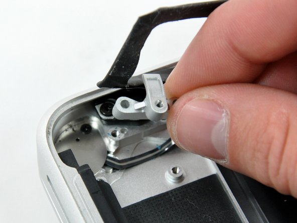
Remove two 3.5 mm Phillips screws securing the bottom case clip to the upper case.
-
Lift the bottom case clip out of the upper case.
My clip is oriented 180 degrees (flipped) from this picture.
The bottom case clip is screwed to a black plastic bracket that's glued onto the upper case. My replacement upper case did not come with this bracket. I had to carefully pry it off the old upper case, taking care not to break it, and glue it to the new upper case before replacing the logic board.
I have a 2.66ghz 15inch Unibody Macbook Pro (A1286) and this step was not necessary.
crwdns2936937:0Andrew Mostajocrwdne2936937:0
I have a 2.66ghz 15inch Unibody Macbook Pro (A1286) and this step (24) was not necessary.
Apropos to the last tip in this step, the replacement unibody I purchased omitted the receiving end of this clip, but it was in my original. As it only captures (but does not secure) a small metal tab on the bottom cover, I skipped transferring it.
Agree with @colleenthompson - mine was also rotated 180 degrees from what is shown, which also matches the other side of the computer.
-
-
-
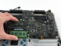
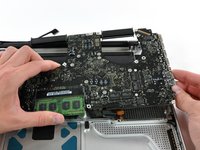
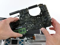
Carefully lift the logic board assembly from the left side and work it out of the upper case, minding the port side that may get caught during removal.
-
-
-
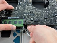
Lift the logic board enough to grab the battery connector and pull it straight away from its socket on the logic board.
-
Lift the logic board assembly out of the upper case.
I didn't have to do this step, I just leaned the logic board up and changed the DC board.
Its better to carefuly “flip” the board towards battery compartment and then take the connector out. The way, how it is written here, its badly accessible with fingers and with tweezers and the connector has plastic point which clicks into hole in the middle of connector. So its better to carefully flip the board upside out and then take it carefully out.
-
-
-
Remove three 2 mm Phillips screws securing the battery connector cover to the upper case.
This whole procedure - removing the battery connector - is NOT NECESSARY! This battery connector is included on the Apple supplied replacement part. DO NOT go through the excessive effort to remove this part if you're getting an Apple part - you'll only end up giving them back an incomplete core part. Boo.
-
-
-
Lift the battery connector cover out of the upper case.
When I took this apart, I was concerned about getting it back together again! I was relieve to see that the replacement upper case came with its own preinstalled battery connector cable and cover.
how do I stick it back? I screwed the battery connector cover on it, but I'm afraid it's not stable enough
Hi Colleen, thanks for this detailed tutorial. I'm trying to put my MacBook Pro together after a major liquid spill, I have done a stupid mistake by removing the trackpad screws, now I can't find/recognize them, could you please point these out? what length/size should they be?
Maxheater, sorry, i don't know, having only worked on one of these. Maybe there's a trackpad tutorial with the info.
crwdns2936937:0colleenthompsoncrwdne2936937:0
Maxheater, sorry, i don't know, having only worked on one of these. Maybe there's a trackpad tutorial with the info.
hi again, I managed to recognize them at last! thankfully :D they're so unique and not what i thought... now i got it back together (the whole lappy) and the screen represents weird yellowish dynamic line shades!! only on certain points, the problem is in a certain degree of grey, it shows as a flicker or a yellowish shade.... have u been through this before?
This whole procedure - removing the battery connector - is NOT NECESSARY! This battery connector is included on the Apple supplied replacement part. DO NOT go through the excessive effort to remove this part if you're getting an Apple part - you'll only end up giving them back an incomplete core part. Boo.
-
-
-
Peel the battery connector cable off the adhesive securing it to the upper case.
-
De-route the battery connector cable through the gap in the upper case and remove it from the computer.
-
-
-
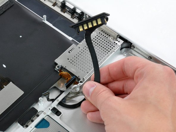
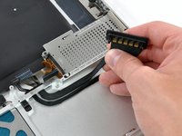
Remove the following screws securing the ExpressCard Cage to the upper case:
-
Two 4 mm Phillips screws.
-
Two 1.9 mm Phillips screws.
-
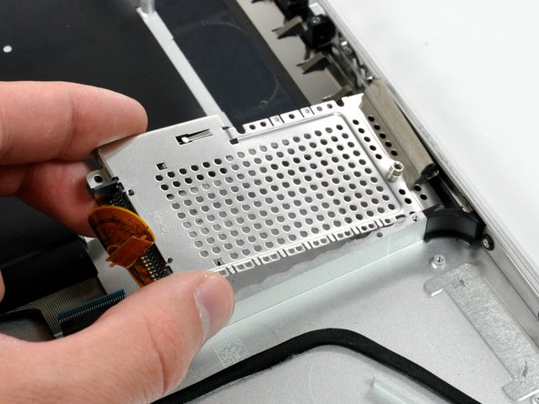
Lift the the ExpressCard Cage out of the upper case.
-
-
-
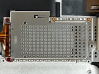
Remove the single Phillips screw securing the hard drive bracket to the upper case.
-
-
-
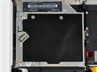
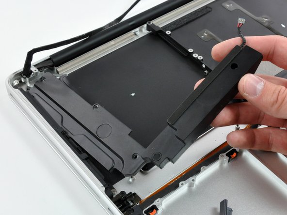
Lift the hard drive by its pull tab enough to grab and remove the retaining bracket.
-
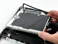
Lift the hard drive out of the upper case, minding the cable attaching it to the computer.
-
-
-
Remove the hard drive from its cable by pulling the cable connector straight away from the drive.
-
-
-
Remove the following three Phillips screws securing the optical drive to the upper case:
-
One 3.5 mm Phillips screw.
-
Two 2.5 mm Phillips screws.
-
Lift the optical drive from its right edge and pull it out of the computer.
... And unstick the "camera cable" (I'd imagine it includes more than just the camera!) from the optical drive first.
-
-
-
Remove the following four screws securing the subwoofer and right speaker to the upper case:
-
Two 3.2 mm Phillips screws.
-
One 2.6 mm Phillips screw.
-
One 5.0 mm Phillips screw.
-
Lift the subwoofer and right speaker assembly out of the upper case.
See the bracket that the right side of the optical drive is screwed to? My replacement upper case did not come with that, so I had to remove it from the bad case and move it to the new one. The instructions leave that out.
This middle bar that screws the optical drive down is NOT included on the Apple supplied replacement part, and SHOULD be removed prior to sending back the old part for a core. Much to my dismay.
-
-
-
Peel the hard drive cable from the adhesive securing it to the upper case, and maneuver the plastic retaining block out of the upper case.
My replacement upper case came with its own preinstalled, preglued hard drive cable.
Same, the Apple supplied replacement part includes a preinstalled, preglued hard drive cable. DO NOT remove this if you're using an Apple part! Just some unnecessary effort in an otherwise perfect guide. :)
-
-
-
Remove two 8 mm Phillips screws securing the camera cable bracket to the upper case.
-
Seperate the camera cable bracket from the camera cable and remove it from the computer.
-
-
-
Remove the 7 mm Phillips screw from the LVDS cable bracket.
-
Lift the LVDS cable bracket out of the upper case.
-
-
-
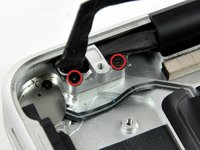
Remove two outer 6 mm T6 Torx screws securing each side of the display to the upper case (4 screws total).
-
-
-
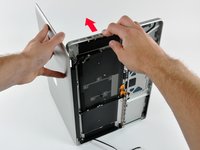
Open your MacBook Pro so the display is perpendicular to the upper case.
-
Place your opened MacBook Pro on a table as pictured.
-
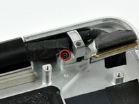
While holding the display and upper case together with your other hand, remove the 6 mm Torx screw from the lower display bracket.
-
-
-
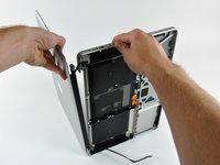
Remove the last remaining 6 mm Torx screw securing the display to the upper case.
-
-
-
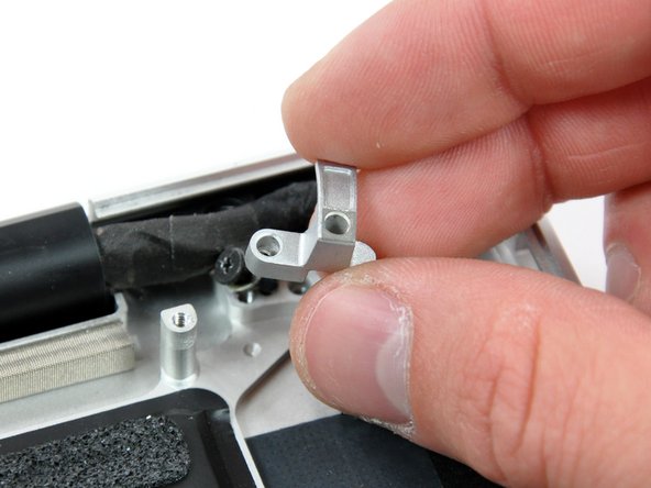
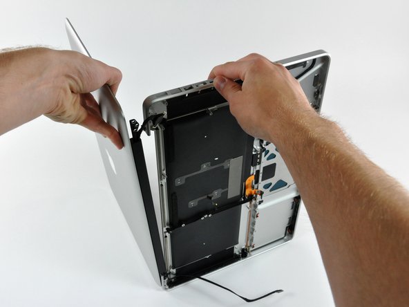
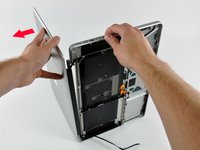
Grab the upper case with your right hand and rotate it slightly toward the top of the display so the upper display bracket clears the edge of the upper case.
-
Rotate the display slightly away from the upper case.
-
Lift the display away from the upper case, minding any brackets or cables that may get caught.
-


To reassemble your device, follow these instructions in reverse order.
To reassemble your device, follow these instructions in reverse order.
crwdns2935221:0crwdne2935221:0
crwdns2935229:045crwdne2935229:0

crwdns2947412:02crwdne2947412:0
This requires a Torx T6 (Step 39) that is not included in the "Required Tools" list.
Thanks Dan. The T6 Torx screwdriver is now part of the required tools list.
The A1286 has no Access Door.!!
I actually can see no sign of the battery!...
aguib - crwdns2934203:0crwdne2934203:0
I assume you have the newer model, with the built-in battery. It's still removable with tools, but these are the wrong instructions for that model.
lgc90 - crwdns2934203:0crwdne2934203:0
when will there be a guide for the other unibody macbook pro. that does not have an access door?
irishking - crwdns2934203:0crwdne2934203:0
Is there a manual to show, how disasembly the display, i mean, after step 5, to check the display between lcd and aluminiun back case?
Max
Max - crwdns2934203:0crwdne2934203:0
On other guides you state the height of the HD that can be supported, e.g. MacBook Pro 15" Core 2 Duo Model A1211 Hard Drive Replacement , I have read ( but have not confirmed ) that the uni-body MacBook Pro can be fitted with the 750GB and 1TB 12mm drive from Western Digital.
Can you confirm this?
Many thanks in advance.
ahothabeth - crwdns2934203:0crwdne2934203:0
My display and aluminum casing has separated.
I don't know if it just snaps back together or does it need to be glued.
I dropped mine on the carpeted stairs and the display still works.
I'm hoping I can just snap it back together and that no plastic pieces or teeth of the snapping
portion have been broken........
SHerwood Ball - crwdns2934203:0crwdne2934203:0
When you say "left fan" is this "left when looking at the logic board after turning the computer over and looking it up opening it up" or "left when sitting at the computer keyboard and typing on it"?
thvv - crwdns2934203:0crwdne2934203:0
We always use left and right in reference to the computer when you're using it.
Andrew Optimus Goldheart -
Directions were great and the worn dc in board was replaced. The hardest part of the procedure is disconnecting the data display cable. A better description of step 21 is to slide the connector parallel to the circuit board towards the outside corner. Reconnecting correctly took several tries.
I used the tip of the spudger to nudge the corners a little at a time to seat the connector.
The ribbon connector for the keyboard has to be inserted all the way before seating the retaining cap. It took me three tries . First try power button did not work second try numbers keys did not work.
Thanks for the directions ...could not have done it with out them!!!
landryd - crwdns2934203:0crwdne2934203:0
Hola. Poseo un MacBook Pro Late 2008 y debo cambiarle las cornetas. Me sirve unas cornetas de un MBP Late 2011?
jegonzalez80 - crwdns2934203:0crwdne2934203:0
Please read the instructions about removing the bluetooth cable - you CAN work around it, and NOT take off the plug.
kenneth krabat - crwdns2934203:0crwdne2934203:0