crwdns2931315:0crwdnd2931315:0crwdne2931315:0
crwdns2942213:0crwdne2942213:0
-
crwdns2935201:0crwdne2935201:0 crwdns2935203:0crwdne2935203:0
-
With the case closed, place the Unibody top-side down on a flat surface.
-
Depress the grooved side of the access door release latch enough to grab the free end. Lift the release latch until it is vertical.
-
-
crwdns2935201:0crwdne2935201:0 crwdns2935203:0crwdne2935203:0
-
The access door should now be raised enough to lift it up and out of the Unibody.
-
-
crwdns2935201:0crwdne2935201:0 crwdns2935203:0crwdne2935203:0
-
Grab the translucent plastic tab and pull the battery up and out of the Unibody.
-
If the latch is depressed it will lock the battery in place.
-
-
-
crwdns2935201:0crwdne2935201:0 crwdns2935203:0crwdne2935203:0
-
Remove the following eight screws securing the lower case to the chassis:
-
One 5.4 mm Phillips screw.
-
Three 14 mm Phillips screws.
-
Four 3.5 mm Phillips screws.
-
-
crwdns2935201:0crwdne2935201:0 crwdns2935203:0crwdne2935203:0
-
Using both hands, lift and remove the lower case off the upper case.
-
-
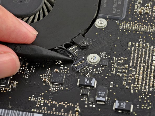
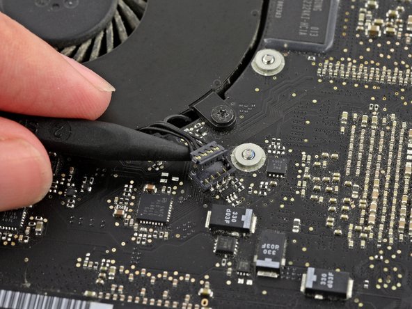
crwdns2935201:0crwdne2935201:0 crwdns2935203:0crwdne2935203:0
-
Use a spudger to pry the fan connector straight up and out of its socket on the logic board.
-
-
crwdns2935201:0crwdne2935201:0 crwdns2935203:0crwdne2935203:0
-
Remove the following three screws securing the right fan to the upper case and logic board:
-
Two 3.2 mm Phillips screws.
-
One 3.5 mm Phillips screw.
-


crwdns2935221:0crwdne2935221:0
crwdns2935229:071crwdne2935229:0

crwdns2917034:0crwdne2917034:0
A great walkthrough.
Once completed, I did a reset of the PRAM, and it all worked beautifully.
Thanks again.