crwdns2915892:0crwdne2915892:0
This motherboard includes all ports on the left side.
crwdns2942213:0crwdne2942213:0
-
-
With the case closed, place the Unibody top-side down on a flat surface.
-
Depress the grooved side of the access door release latch enough to grab the free end. Lift the release latch until it is vertical.
-
-
-
The access door should now be raised enough to lift it up and out of the Unibody.
-
-
-
Grab the translucent plastic tab and pull the battery up and out of the Unibody.
-
If the latch is depressed it will lock the battery in place.
-
-
-
Remove the following eight screws securing the lower case to the chassis:
-
One 5.4 mm Phillips screw.
-
Three 14 mm Phillips screws.
-
Four 3.5 mm Phillips screws.
-
-
-
Using both hands, lift and remove the lower case off the upper case.
-
-
-
Remove the following 5 screws securing the mid wall to the upper case:
-
Three 10.5 mm Phillips screws.
-
Two 3.7 mm Phillips screws.
-
-
-
Lift the mid wall out of the upper case.
-
-
-
Remove the following six screws securing both the right fan and the left fan to the logic board:
-
Four 3.5 mm Phillips screws.
-
Two 3.2 mm Phillips screws.
-
-
-
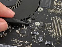
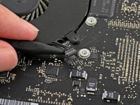
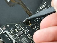
Use the tip of a spudger to lift the right fan connector straight up from its socket on the logic board.
-
Remove the right fan from the case.
-
-
-
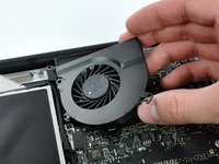
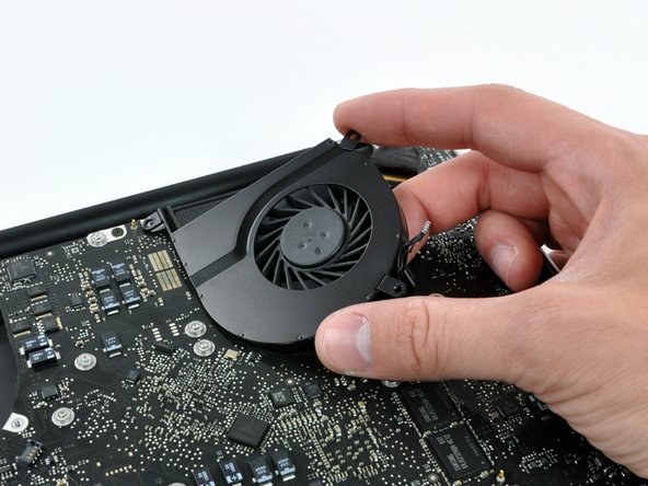
Use the tip of a spudger to lift the left fan connector straight up from its socket on the logic board.
-
Remove the left fan from the case.
-
-
-
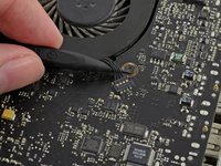
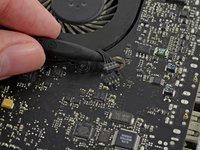
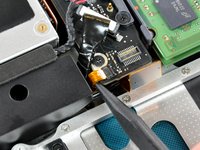
Remove any adhesive from the camera cable connector.
-
Disconnect the camera cable by pulling the male end out of its socket, parallel to the logic board, do not lift it upwards.
-
-
-
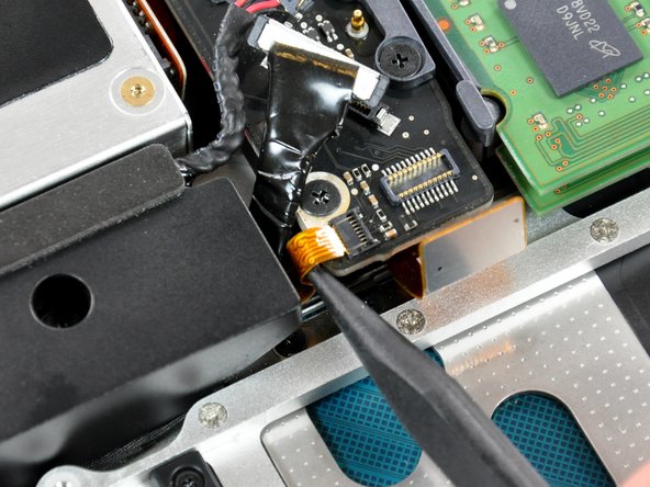
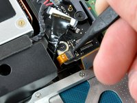
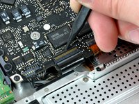
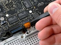
Use a spudger to carefully pry the optical drive connector straight up off its socket on the logic board.
-
-
-
-
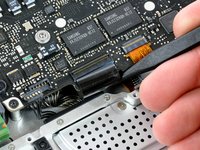
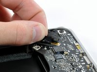
Using the flat end of a spudger, pry the subwoofer connector straight up off its socket on the logic board.
-
-
-
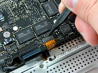
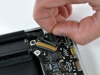
Use the flat end of a spudger to pry the silver-colored hard drive cable connector straight up out of its socket on the logic board.
-
-
-
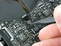
Use a spudger to pry the trackpad connector straight up out of its socket on the logic board.
-
-
-
Using the tip of a spudger, flip up the IR/sleep LED ribbon cable retaining flap.
-
Pull the IR/sleep LED ribbon cable straight out of its socket.
-
-
-
Use a spudger to pry the battery indicator light connector straight up out of its socket on the logic board.
-
-
-
Using the tip of a spudger, flip up the keyboard ribbon cable retaining flap.
-
Pull the keyboard ribbon cable straight out of its socket.
-
-
-
Using the tip of a spudger, flip up the express card cage ribbon cable retaining flap.
-
Pull the express card cage ribbon cable straight out of its socket.
-
-
-
Using the flat end of a spudger, pry the microphone cable connector straight up out of its socket on the logic board.
-
-
-
Grab the plastic pull tab secured to the display data cable lock and rotate it toward the DC-in side of the computer.
-
Pull the display data cable connector straight away from its socket.
-
-
-
Locate the keyboard backlight ribbon cable (near the left fan space).
-
Using the tip of a spudger, flip up the keyboard backlight ribbon cable retaining flap.
-
Pull the keyboard backlight ribbon cable straight out of its socket.
-
-
-
Remove seven 3.2 mm Phillips screws securing the logic board to the upper case.
-
-
-
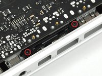
Remove two 7 mm Phillips screws securing the DC-in board to the upper case.
-
-
-
Remove two 3.5 mm Phillips screws securing the bottom case clip to the upper case.
-
Lift the bottom case clip out of the upper case.
-
-
-
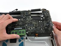
Carefully lift the logic board assembly from the left side and work it out of the upper case, minding the port side that may get caught during removal.
-
-
-
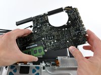
Lift the logic board enough to grab the battery connector and pull it straight away from its socket on the logic board.
-
Lift the logic board assembly out of the upper case.
-
-
-
Remove eight 8.4 mm Phillips screws securing the heat sink to the logic board.
-
-
-
Use the tip of a spudger to pry the thermal sensor connector up off the logic board.
-
-
-
Gently lift the heat sink off the logic board.
-
-
-
Remove the two 5 mm Phillips screws securing the left speaker to the logic board.
-
-
-
Use the flat end of a spudger to pry the left speaker connector up off the logic board.
-
-
-
Lift the left speaker assembly out of the logic board.
-
-
-
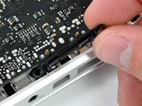
Disconnect the DC-In Board connector from the logic board by pulling it straight away from its socket.
-
-
-
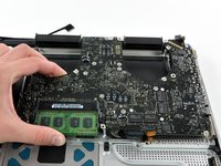
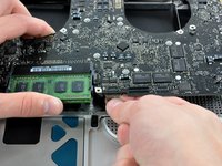
Release the tabs on each side of the RAM chip by simultaneously pushing each tab away from the chip.
-
-
-
After the RAM chip has popped up, pull it straight out of its socket.
-


To reassemble your device, follow these instructions in reverse order.
crwdns2935221:0crwdne2935221:0
crwdns2935229:058crwdne2935229:0

crwdns2947412:011crwdne2947412:0
I have a late 2008, 2.4Ghz, core 2 duo, 15" , unibody, MB470LL/A, MacBook Pro5,1. My current board has the following ports on the left:
Mag safe
Ethernet
FireWire 800
USB (x2)
Mini display port
Mic
Headphone
I just want to verify that any of the boards (2.4, 2.53, 2.66, 2.8, 2.93), will work. I figure as long as I'm replacing the board, why not upgrade CPU and RAM capacity. Any insight would be deeply appreciated!
What did you end up installing?
c cs -
Any advice for someone who stripped a screw each on the fans. I can't get them out.
Original Deutch:
Mein MacBook Pro (MacBook Pro 15" Unibody Late 2008) funktioniert schon länger nicht mehr. Es startete nicht mehr und zeigte, bis auf die Akkuanzeige, keine Lebenszeichen. Vor kurzem habe ich mit einen Reparaturversuch gestartet. Jetzt habe ich das Logic Board vor mir und finde nichts eindeutig beschädigtes. Das einzige was ich sehe ist das die Aufgelötete Batterie kein Saft mehr hat. Ich finde zu dieser jedoch keine Informationen. Mit was tausche ich diese aus?
Google English:
My MacBook Pro (MacBook Pro 15 "Unibody Late 2008) has been running for a while, it stopped booting and showed no sign of life, except for the battery indicator I recently started a repair attempt Now I have the logic board in front of me The only thing I can see is that the soldered battery has no juice left, but I can not find any information about it, so what do I swap it with?