crwdns2915892:0crwdne2915892:0
The heat sink helps keep the processor cool and happy. Be sure to replace the thermal paste before reinstalling the heat sink.
crwdns2942213:0crwdne2942213:0
-
-
With the case closed, place the Unibody top-side down on a flat surface.
-
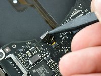
Depress the grooved side of the access door release latch enough to grab the free end. Lift the release latch until it is vertical.
-
-
-
The access door should now be raised enough to lift it up and out of the Unibody.
-
-
-
Grab the translucent plastic tab and pull the battery up and out of the Unibody.
-
If the latch is depressed it will lock the battery in place.
-
-
-
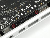
Remove the following eight screws securing the lower case to the chassis:
-
One 5.4 mm Phillips screw.
-
Three 14 mm Phillips screws.
-
Four 3.5 mm Phillips screws.
-
-
-
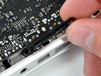
Using both hands, lift and remove the lower case off the upper case.
-
-
-
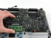
Remove the following 5 screws securing the mid wall to the upper case:
-
Three 10.5 mm Phillips screws.
-
Two 3.7 mm Phillips screws.
-
-
-
Lift the mid wall out of the upper case.
-
-
-
Remove the following six screws securing both the right fan and the left fan to the logic board:
-
Four 3.5 mm Phillips screws.
-
Two 3.2 mm Phillips screws.
-
-
-
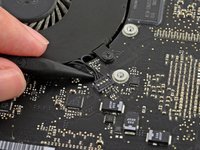
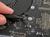
Use the tip of a spudger to lift the right fan connector straight up from its socket on the logic board.
-
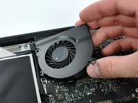
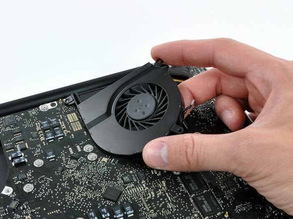
Remove the right fan from the case.
-
-
-
Use the tip of a spudger to lift the left fan connector straight up from its socket on the logic board.
-
Remove the left fan from the case.
-
-
-
-
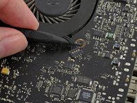
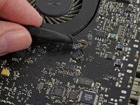
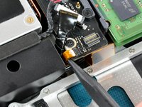
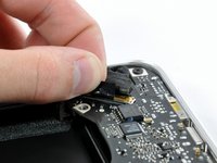
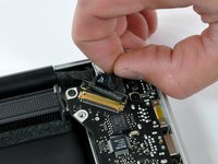
Remove any adhesive from the camera cable connector.
-
Disconnect the camera cable by pulling the male end out of its socket, parallel to the logic board, do not lift it upwards.
-
-
-
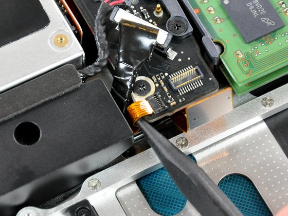
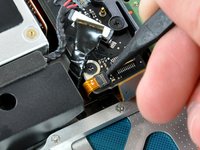
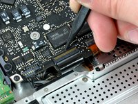
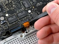
Use a spudger to carefully pry the optical drive connector straight up off its socket on the logic board.
-
-
-
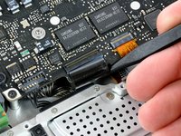
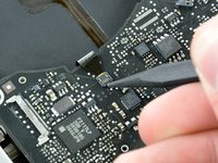
Using the flat end of a spudger, pry the subwoofer connector straight up off its socket on the logic board.
-
-
-
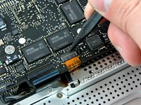
Use the flat end of a spudger to pry the silver-colored hard drive cable connector straight up out of its socket on the logic board.
-
-
-
Use a spudger to pry the trackpad connector straight up out of its socket on the logic board.
-
-
-
Using the tip of a spudger, flip up the IR/sleep LED ribbon cable retaining flap.
-
Pull the IR/sleep LED ribbon cable straight out of its socket.
-
-
-
Use a spudger to pry the battery indicator light connector straight up out of its socket on the logic board.
-
-
-
Using the tip of a spudger, flip up the keyboard ribbon cable retaining flap.
-
Pull the keyboard ribbon cable straight out of its socket.
-
-
-
Using the tip of a spudger, flip up the express card cage ribbon cable retaining flap.
-
Pull the express card cage ribbon cable straight out of its socket.
-
-
-
Using the flat end of a spudger, pry the microphone cable connector straight up out of its socket on the logic board.
-
-
-
Grab the plastic pull tab secured to the display data cable lock and rotate it toward the DC-in side of the computer.
-
Pull the display data cable connector straight away from its socket.
-
-
-
Locate the keyboard backlight ribbon cable (near the left fan space).
-
Using the tip of a spudger, flip up the keyboard backlight ribbon cable retaining flap.
-
Pull the keyboard backlight ribbon cable straight out of its socket.
-
-
-
Remove seven 3.2 mm Phillips screws securing the logic board to the upper case.
-
-
-
Remove two 7 mm Phillips screws securing the DC-in board to the upper case.
-
-
-
Remove two 3.5 mm Phillips screws securing the bottom case clip to the upper case.
-
Lift the bottom case clip out of the upper case.
-
-
-
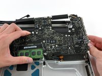
Carefully lift the logic board assembly from the left side and work it out of the upper case, minding the port side that may get caught during removal.
-
-
-
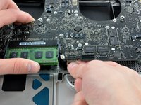
Lift the logic board enough to grab the battery connector and pull it straight away from its socket on the logic board.
-
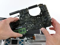
Lift the logic board assembly out of the upper case.
-
-
-
Remove eight 8.4 mm Phillips screws securing the heat sink to the logic board.
-
-
-
Use the tip of a spudger to pry the thermal sensor connector up off the logic board.
-
-
-
Gently lift the heat sink off the logic board.
-


To reassemble your device, follow these instructions in reverse order.
crwdns2935221:0crwdne2935221:0
crwdns2935229:028crwdne2935229:0

crwdns2947412:04crwdne2947412:0
Wonder why there are springs on the heat sink screws? Do not over tighten them, the springs are there to help you apply the correct amount of pressure on to the CPU and GPU. If you tighten them all the way, it may not be the correct pressure! Leave maybe 1 mm of space, just before the screw stops turning. iFixit forgot to mention this important part, and also in the heat paste guide!!
My Macbook was over heating. i did these steps to put thermal paste but now my Macbook pro is not even opening.. please help..!!
My old Macbook was getting pretty hot (90-110 C on the main processor temperature sensor) doing normal tasks so I decided it was probably the thermal paste going bad. Successfully completed this using this guide, typing this on that computer now, thanks! It took me about 3 hours all in, including setup and cleanup afterwards. I did not replace the heat pipe assembly itself, just redid the thermal paste. I am actually curious what the symptoms are that would lead to completely replacing the heat pipe assembly itself. Running much cooler now (59 C).
I went through this last night to the T, made sure to be careful and put all cables back properly. Now when I start the laptop I get the startup noise, the screen will flicker really quick but then go back to black and stays black indefinitely. The keyboard lights come on and the laptop is running fine just no display. I’ve tried all the resetting pram and all of that to no avail. I have reseated the lcd cable multiple times and still have a black screen. At a loss.