crwdns2915892:0crwdne2915892:0
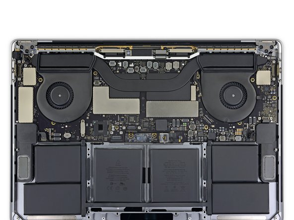
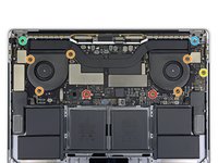
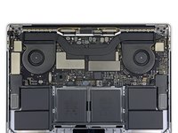
Prerequisite only. Follow this guide to remove the logic board and heat sink together as a single assembly, either for further disassembly or simply to get it out of the way.
crwdns2942213:0crwdne2942213:0
-
-
Power on your Mac and launch Terminal.
-
Copy and paste the following command (or type it exactly) into Terminal:
-
sudo nvram AutoBoot=%00
-
Press [return]. If prompted, enter your administrator password and press [return] again. Note: Your return key may also be labeled ⏎ or "enter."
-
sudo nvram AutoBoot=%03
-
-
crwdns2935267:0crwdne2935267:0Magnetic Project Mat$19.95
-
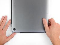
Close the display and flip the entire laptop upside-down.
-
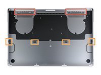
Use a P5 Pentalobe driver to remove six screws securing the lower case, of the following lengths:
-
Four 4.7 mm screws
-
Two 6.6 mm screws
-
-
-
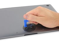
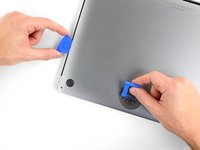
Press a suction handle into place near the front edge of the lower case, between the screw holes.
-
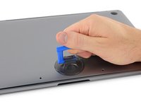
Lift up on the suction handle just enough to open a small gap under the lower case.
-
-
-
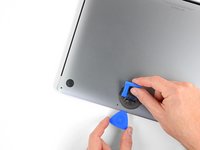
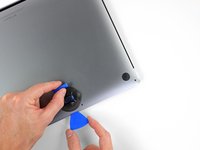
Slide the corner of an opening pick into the gap you just created underneath the lower case.
-
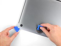
Slide the opening pick around the nearest corner and then halfway up the side of the MacBook Pro.
-
-
-
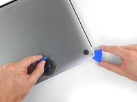
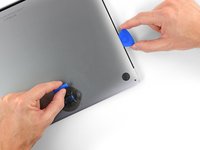
Repeat the previous step on the opposite side, using your opening pick to release the second clip.
-
-
-
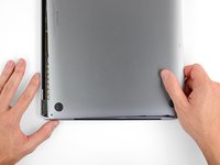
Lift the front edge of the lower case (the side opposite the display hinge) just enough to slide your fingertips underneath and get a good grip on it.
-
-
-
Pull the lower case firmly towards the front of the MacBook (away from the hinge area) to separate the last of the clips securing the lower case.
-
Pull first at one corner, then the other.
-
-
-
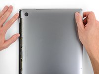
Remove the lower case.
-
Set it in place and align the sliding clips near the display hinge. Press down and slide the cover toward the hinge. It should stop sliding as the clips engage.
-
When the sliding clips are fully engaged and the lower case looks correctly aligned, press down firmly on the lower case to engage the four hidden clips. You should feel and hear them click into place.
-
-
-
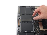
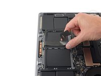
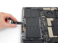
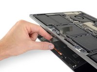
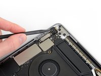
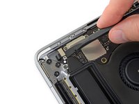
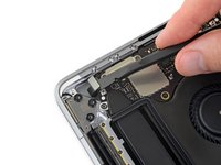
Peel up and remove the large rectangular battery board cover, on the edge of the logic board nearest the battery.
-
If the cover doesn't peel up easily, apply mild heat with an iOpener, hair dryer, or heat gun to soften the adhesive underneath, and try again.
-
-
-
Peel back the tape covering the battery board data cable connector.
-
-
-
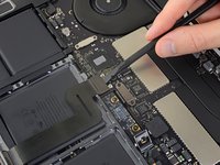
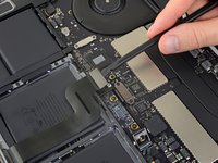
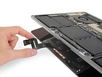
Use a spudger to gently pry up the locking flap on the ZIF connector for the battery board data cable.
-
-
-
Disconnect the battery board data cable by sliding it out from its socket.
-
Slide parallel to the logic board, in the direction of the cable.
-
-
-
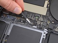
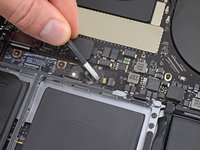
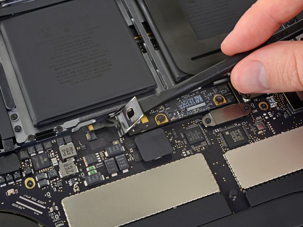
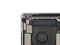
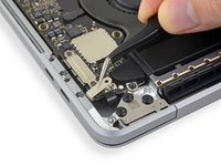
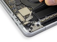
Use a T5 Torx driver to remove the 3.7 mm pancake screw securing the battery power connector.
-
-
-
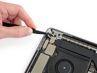
Use a spudger to gently lift the battery power connector, disconnecting the battery.
-
-
-
Use a T3 Torx driver to remove the two 1.9 mm screws securing the trackpad cable's cover bracket.
-
Remove the bracket.
-
-
-
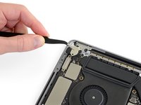
Use a spudger to disconnect the trackpad cable by prying its connector straight up from the logic board.
-
-
-
Apply mild heat to the trackpad ribbon cable to soften the adhesive securing it to the battery.
-
You can use an iOpener, hair dryer, or heat gun, but be careful not to overheat the battery. The cable should be warm, but not too hot to touch.
-
-
-
-
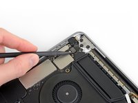
Carefully peel the trackpad cable up off the battery, and push it out of the way.
-
-
-
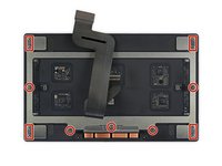
Use a T5 Torx driver to remove the 13 screws securing the trackpad assembly:
-
Nine 5.8 mm screws
-
Four 4.9 mm screws
-
-
-
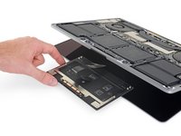
Swing the display open slightly, but keep the MacBook upside-down. The trackpad assembly should separate and lay flat on the display.
-
Gently feed the trackpad's ribbon cable through its slot in the chassis.
-
-
-
As you remove the trackpad assembly, be very careful not to lose the nine small metal washers resting on the screw posts. (They will fly off and get lost with very little provocation.)
-
Remove the trackpad assembly.
-
-
-
Using a T3 Torx driver, remove the two 1.9 mm screws securing the keyboard connector cover bracket.
-
Remove the bracket.
-
-
-
Use your spudger to disconnect the keyboard by prying its connector straight up from the logic board.
-
-
-
Use a T3 Torx driver to remove the two 3.5 mm screws securing the cover on the display board flex cable.
-
Remove the display board flex cable cover.
-
-
-
Use a T3 Torx driver to remove the two 1.7 mm screws securing the bracket for the display board cable connector.
-
Remove the bracket from the display board cable connector.
-
-
-
Pry straight up with your spudger to disconnect the display board flex cable.
-
-
-
Use a T3 Torx driver to remove the two 2.0 mm screws securing each hinge cover (four screws total).
-
-
-
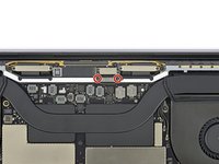
Use a T3 Torx driver to remove the two 2.4 mm screws securing the cover bracket for the Touch ID and headphone jack cable connectors.
-
Remove the bracket.
-
-
-
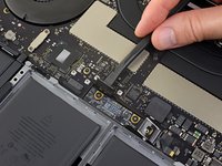
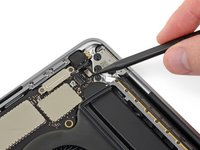
Disconnect the headphone jack cable by prying its connector straight up from the logic board.
-
-
-
Disconnect the power button and Touch ID sensor by prying its connector straight up from the logic board.
-
-
-
Use a T3 Torx driver to remove the 1.3 mm screw securing the cover bracket for the Touch Bar digitizer connector.
-
-
crwdns2935267:0crwdne2935267:0Tweezers$4.99
-
Using your tweezers, slide the bracket toward the side edge of the MacBook Pro until it clears the slotted retaining tab on the logic board.
-
Remove the bracket.
-
-
-
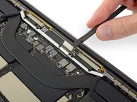
Disconnect the Touch Bar digitizer cable by prying it straight up from the logic board.
-
-
-
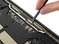
Use a T3 Torx driver to remove the two 1.9 mm screws securing the bracket for the Touch Bar display cable connector.
-
Remove the bracket.
-
-
-
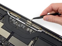
Disconnect the Touch Bar display cable by prying its connector straight up from the logic board.
-
-
-
Use a T3 Torx driver to remove the four 1.3 mm screws securing the Thunderbolt flex cable covers:
-
Two screws on the left
-
Two more on the right
-
-
-
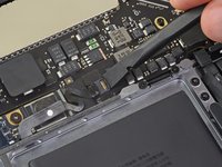
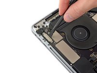
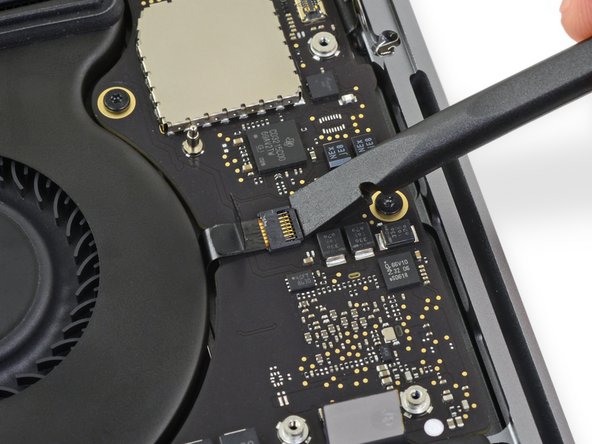
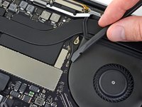
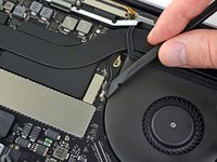
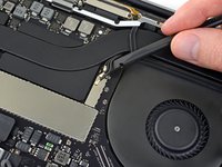
Disconnect the left-side Thunderbolt flex cable by prying it straight up from the logic board.
-
Pry from the inside edge, nearest the fan.
-
Gently push the flex cable connector off to the side so it doesn't interfere with logic board removal.
-
-
-
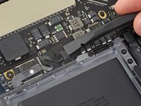
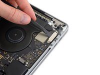
Repeat to disconnect the Thunderbolt flex cable connector on the opposite side.
-
Carefully push the flex cable connector aside so there's clearance for the logic board to come out without snagging.
-
-
-
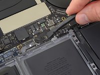
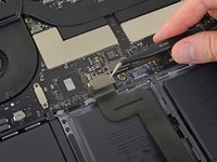
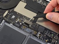
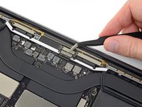
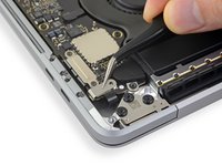
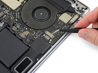
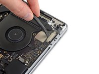
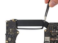
Disconnect the two speaker connectors by sliding the flat end of your spudger underneath each cable near its connector.
-
Gently twist or pry up to disconnect both speakers.
-
-
-
Peel up any tape covering the microphone cable connector socket.
-
-
-
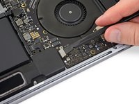
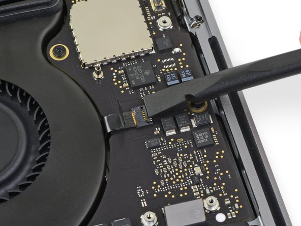
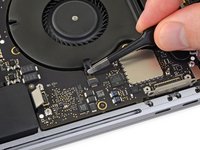
Open the locking flap on the microphone cable's ZIF connector by prying it straight up from the logic board.
-
-
-
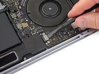
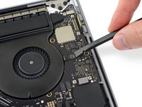
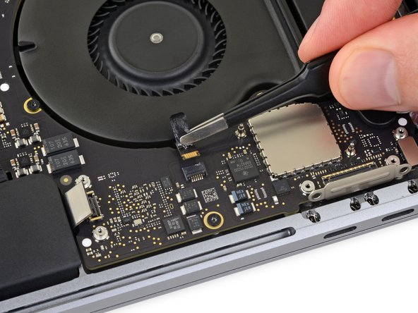
Disconnect the microphone by pulling its cable toward the fan until it releases from its socket.
-
If possible, pull on the tape attached to the cable, rather than the cable itself, to reduce the risk of damage.
-
-
-
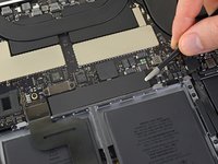
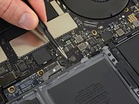
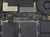
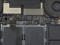
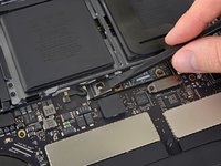
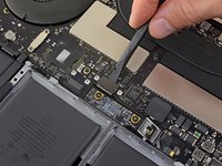
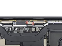
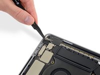
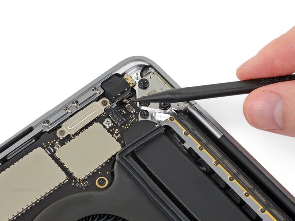
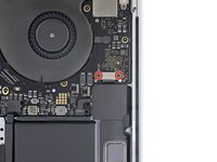
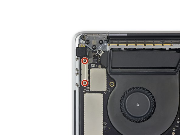
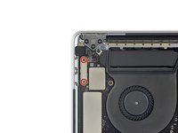
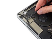
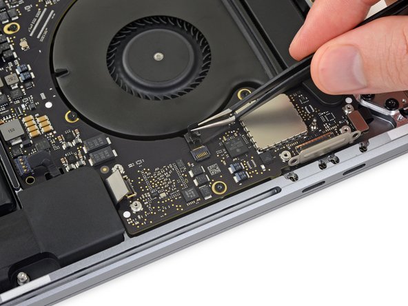
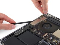
Use a T5 Torx driver to remove the single 2.9 mm screw securing the antenna cable bundle.
-
-
-
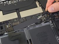
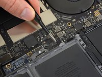
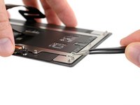
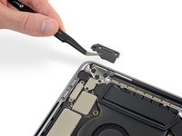
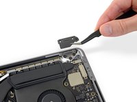
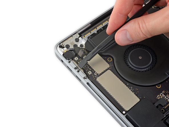
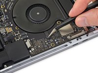
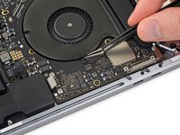
Disconnect all three antenna cables by prying each one straight up from its socket.
-
Slide your tweezers or the flat end of your spudger underneath each cable until it's near the socket, and then gently twist or pry up to disconnect it.
-
-
-
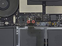
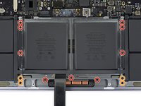
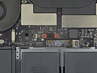
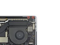
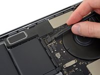
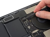
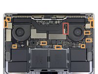
Remove the ten screws securing the logic board assembly:
-
Two 2.8 mm T3 Torx screws
-
Five 2.9 mm T5 Torx screws
-
One 3.7 mm T5 Torx screw
-
One 3.9 mm T8 Torx screw
-
One 3.8 mm T8 Torx screw
-
-
-
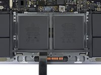
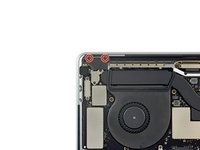
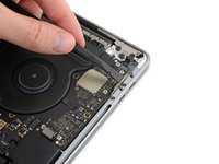
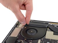
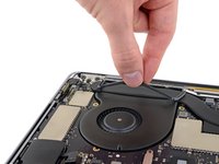
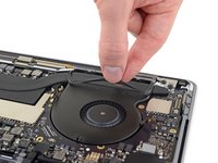
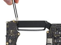
Peel up (but don't remove) the two rubber vibration damping strips from the adhesive holding them to the fans.
-
If needed, apply mild heat with an iOpener, hair dryer, or heat gun to soften the adhesive and make the dampers easier to separate.
-
-
-
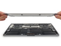
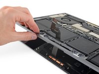
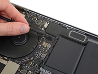
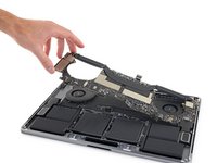
Lifting from the left side, remove the logic board.
-
-
-
Check the alignment of the rubber vibration dampers, and adjust them as needed.
-
Feed the antenna cable bundle through the gap between the logic board and heat sink, and make sure it lines up correctly as you lower the board into place.
-
Verify that no cables get trapped under the board as you install it. Check each marked location carefully.
-


To reassemble your device, follow these instructions in reverse order.
To reassemble your device, follow these instructions in reverse order.

