crwdns2915892:0crwdne2915892:0
Prerequisite to remove the logic board assembly (logic board + heat sink, airport card, etc). Used for logic board and upper case guides.
crwdns2942213:0crwdne2942213:0
-
-
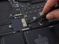
Remove the two 2.2 mm Torx T5 screws securing the touchpad cable connector cover to the logic board.
-
Remove the cover.
-
-
-
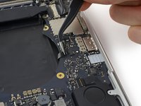
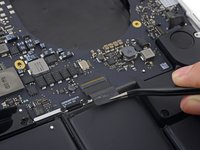
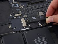
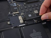
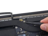
Use the flat end of a spudger to disconnect the touchpad cable connector from its socket in the logic board.
-
-
-
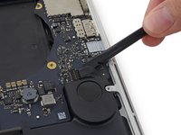
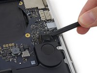
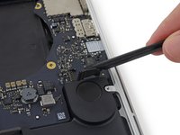
Remove a small rubber cap off the screw at the end of the heat sink.
-
-
-
Remove the following six screws securing the logic board assembly to the upper case.
-
One 3.8 mm T5 Torx screw
-
Two 5.7 mm T5 Torx screws
-
One 5.6 mm T5 Torx screw (this one is silver and has a taller head than the others)
-
One 2.6 mm T5 Torx screw
-
One 3.2 mm T5 Torx screw
-
-
-
The following steps will detail disconnecting these six connectors. Be sure to read each step, as these connectors come in different styles that disconnect differently.
-
Microphone cable
-
Left speaker cable
-
Keyboard data cable
-
Right speaker cable
-
Keyboard backlight cable
-
Display data cable
-
-
-
-
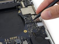
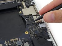
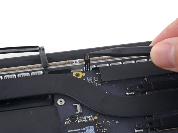
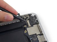
Use the tip of a spudger to flip up the retaining flap on the microphone ribbon cable ZIF socket.
-
Pull the microphone ribbon cable out of its socket, parallel to the logic board.
-
-
-
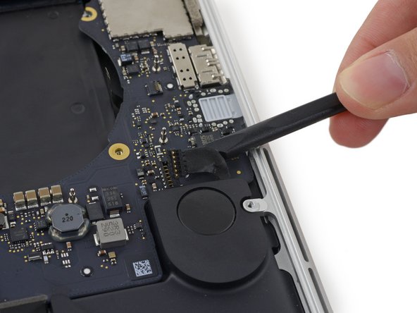
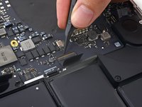
Use the flat end of a spudger to pry the left speaker connector up and out of its socket on the logic board.
-
Gently fold the cable up and out of the way of the logic board.
-
-
-
Peel back the tape covering the top of the keyboard data cable connector.
-
-
-
Use the tip of a spudger to flip up the retaining flap on the keyboard data cable ZIF socket.
-
Pull the keyboard data cable out of its ZIF socket. Be sure to pull parallel to the logic board, and not straight up.
-
-
-
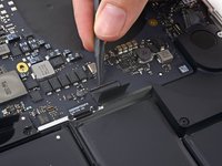
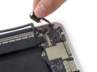
Use the tip of a spudger to pry the right speaker connector up and out of its socket on the logic board.
-
Gently fold the cable up and out of the way of the logic board.
-
-
-
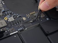
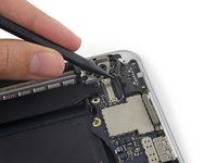
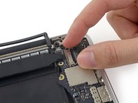
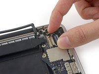
Use the point of a spudger to pry the keyboard backlight connector up from its socket on the logic board.
-
-
-
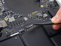
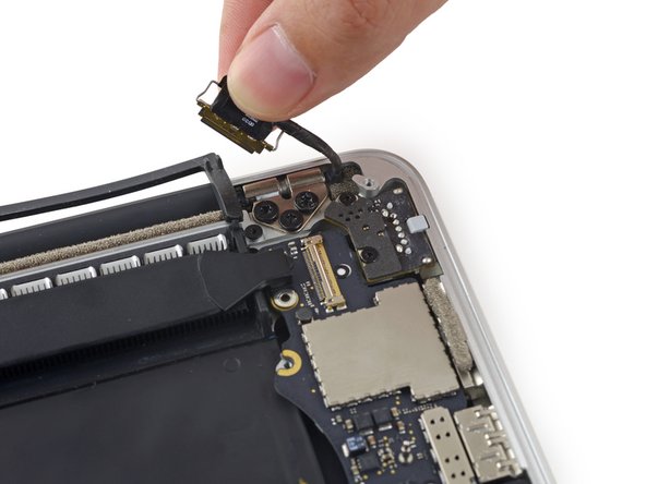
Use the tip of a spudger to flip up the display data cable lock and rotate it toward the MagSafe 2 power port side of the computer.
-
-
-
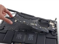
Pull the display data cable straight out of its socket on the logic board.
-
Gently bend the display data cable toward the display hinge, to expose the screws on the MagSafe 2 board.
-
-
-
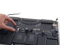
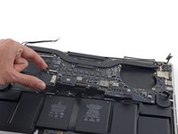
Remove the two 4.0 mm T5 Torx screws from the MagSafe 2 board.
-
-
-
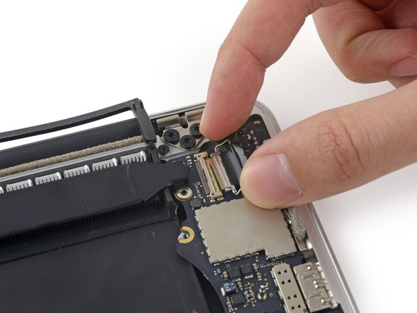
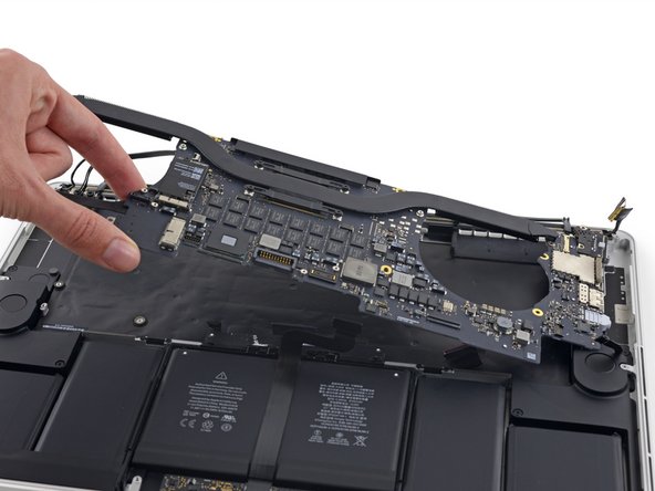
Lift and pull the entire logic board assembly away from the wall of the upper case.
-


To reassemble your device, follow these instructions in reverse order.
To reassemble your device, follow these instructions in reverse order.
crwdns2935221:0crwdne2935221:0
crwdns2935229:02crwdne2935229:0
