crwdns2915892:0crwdne2915892:0
Hearing things? Not hearing things? Use this guide to replace the left speaker in your 15" Mid 2015 MacBook Pro Retina.
Note that the left speaker is on the left of the machine while you're using it, and on the right while you're working on it.
crwdns2942213:0crwdne2942213:0
-
-
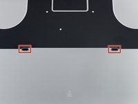
Remove the following P5 pentalobe screws securing the lower case to the MacBook Pro:
-
Eight 3.1 mm
-
Two 2.3 mm
-
-
-
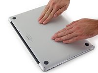
Lifting from the edge nearest the clutch cover, lift the lower case off the MacBook Pro.
-
-
-
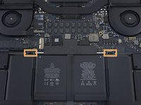
Peel back the sticker covering the battery connector.
-
-
-
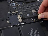
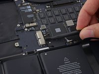
Gently lift each side of the battery connector to pry the connector out of its socket on the logic board.
-
Bend the connector back toward the battery, ensuring that the battery connector doesn't accidentally make contact with the logic board.
-
-
crwdns2935267:0crwdne2935267:0Tweezers$4.99
-
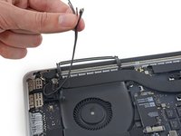
Use a spudger or tweezers to pry the three AirPort antenna cables straight up off of their sockets on the AirPort board, and bend them up and out of the way.
-
-
-
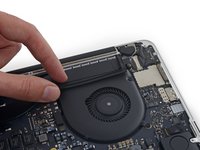
Peel the right rubber cover up off the fan and fold it out of the way.
-
-
-
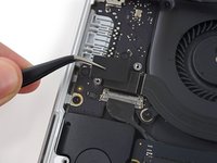
Use the tip of a spudger to push the camera cable connector out of its socket on the logic board.
-
-
-
Use your fingers to pull the AirPort/Camera cables up off the fan.
-
Carefully de-route the cables from the plastic cable guide.
-
-
-
Remove the four 2.2 mm T5 Torx screws securing the I/O board cable connector covers.
-
-
-
Remove the left connector cover.
-
Use the flat end of a spudger to pry the left end of the I/O board cable up from its socket on the logic board.
-
-
-
Remove the right connector cover.
-
Use the flat end of a spudger to pry the right end of the I/O board cable up from its socket on the logic board.
-
-
-
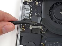
Peel the I/O board cable up from the adhesive securing it to the fan.
-
Remove the cable.
-
-
-
Use a T5 Torx driver to remove the following three screws securing the right fan to the logic board:
-
One 5.0 mm screw with a 2.0 mm long shoulder
-
One 4.0 mm screw with a wide head
-
One 4.4 mm screw
-
-
-
-
Use the tip of a spudger to flip up the retaining flap on the right fan ribbon cable ZIF socket.
-
-
-
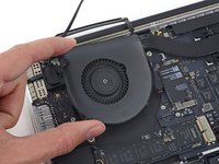
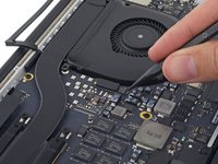
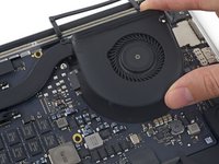
Lift the fan and push it gently towards the back edge of the MacBook to free the fan cable from its socket.
-
Remove the fan.
-
-
-
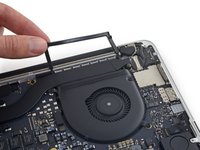
Peel the left rubber cover up off the fan and fold it out of the way.
-
-
-
Remove the following three screws securing the left fan to the logic board:
-
One 3.6 mm T5 Torx screw with a wide head
-
One 5.0 mm T5 Torx screw with a 2.0 mm long shoulder
-
One 4.4 mm T5 Torx screw
-
-
-
Use the tip of a spudger to flip up the retaining flap on the left fan ribbon cable ZIF socket.
-
-
-
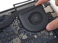
Lift the fan and push it gently towards the back edge of the MacBook to free the fan cable from its socket.
-
Remove the fan.
-
-
-
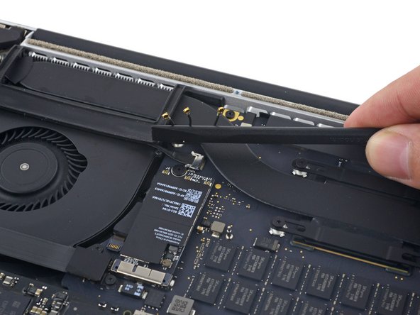
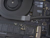
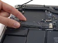
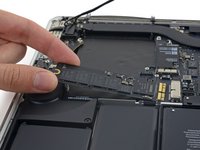
Remove the single 2.9 mm T5 Torx screw securing the SSD to the logic board.
-
-
-
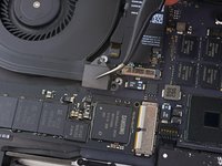
Lift the end of the SSD up enough to pass over the speaker directly behind it.
-
Pull the SSD straight out of its socket on the logic board.
-
-
-
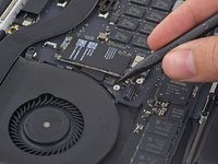
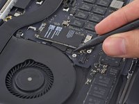
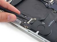
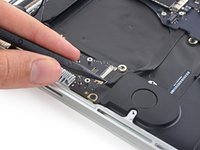
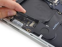
Use the point of a spudger to flip up the locking mechanism on the I/O board connector.
-
Flip the spudger around and use the flat end to slide the I/O cable out of the connector.
-
-
-
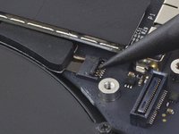
Remove the two 3.1 mm T5 Torx screws from the I/O board.
-
-
-
Slightly lift the interior edge of the I/O board and pull it toward the center of the MacBook, away from the side of the case.
-
Remove the I/O board.
-
-
-
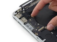
Remove the two 2.2 mm Torx T5 screws securing the touchpad cable connector cover to the logic board.
-
Remove the cover.
-
-
-
Use the flat end of a spudger to disconnect the touchpad cable connector from its socket in the logic board.
-
-
-
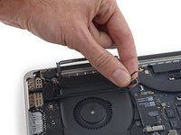
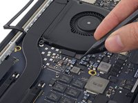
Remove a small rubber cap off the screw at the end of the heat sink.
-
-
-
Remove the following six screws securing the logic board assembly to the upper case.
-
One 3.8 mm T5 Torx screw
-
Two 5.7 mm T5 Torx screws
-
One 5.6 mm T5 Torx screw (this one is silver and has a taller head than the others)
-
One 2.6 mm T5 Torx screw
-
One 3.2 mm T5 Torx screw
-
-
-
The following steps will detail disconnecting these six connectors. Be sure to read each step, as these connectors come in different styles that disconnect differently.
-
Microphone cable
-
Left speaker cable
-
Keyboard data cable
-
Right speaker cable
-
Keyboard backlight cable
-
Display data cable
-
-
-
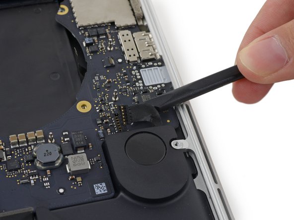
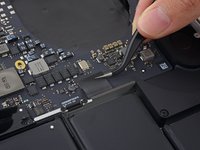
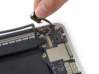
Use the tip of a spudger to flip up the retaining flap on the microphone ribbon cable ZIF socket.
-
Pull the microphone ribbon cable out of its socket, parallel to the logic board.
-
-
-
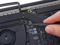
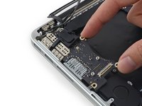
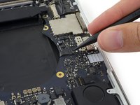
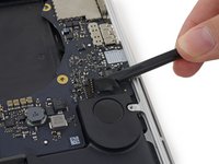
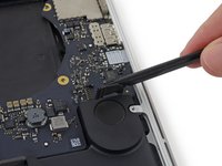
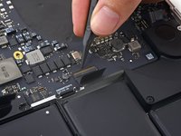
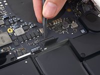
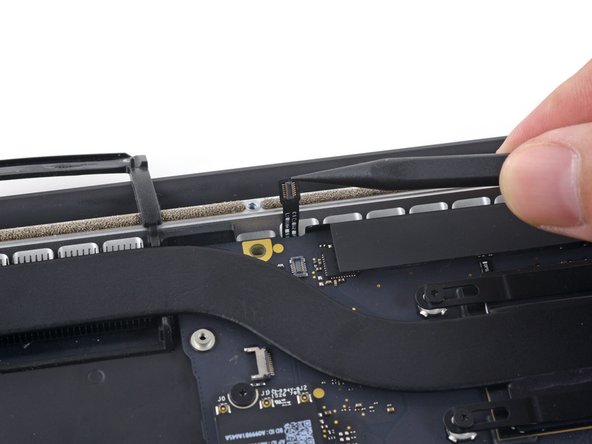
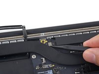
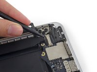
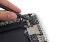
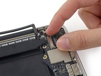
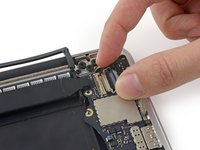
Use the flat end of a spudger to pry the left speaker connector up and out of its socket on the logic board.
-
Gently fold the cable up and out of the way of the logic board.
-
-
-
Peel back the tape covering the top of the keyboard data cable connector.
-
-
-
Use the tip of a spudger to flip up the retaining flap on the keyboard data cable ZIF socket.
-
Pull the keyboard data cable out of its ZIF socket. Be sure to pull parallel to the logic board, and not straight up.
-
-
-
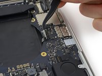
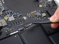
Use the tip of a spudger to pry the right speaker connector up and out of its socket on the logic board.
-
Gently fold the cable up and out of the way of the logic board.
-
-
-
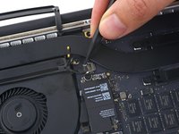
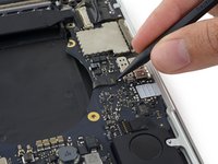
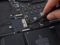
Use the point of a spudger to pry the keyboard backlight connector up from its socket on the logic board.
-
-
-
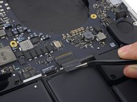
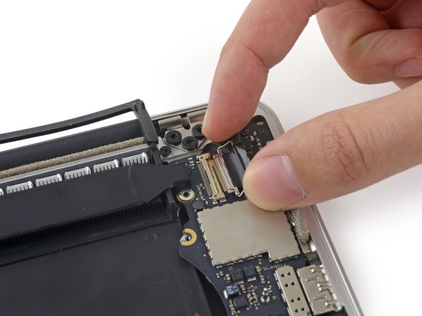
Use the tip of a spudger to flip up the display data cable lock and rotate it toward the MagSafe 2 power port side of the computer.
-
-
-
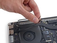
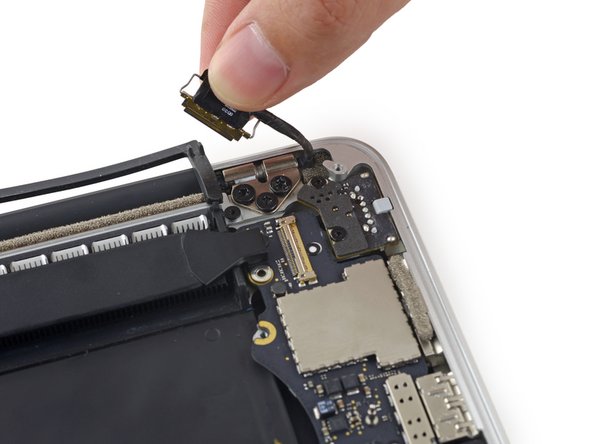
Pull the display data cable straight out of its socket on the logic board.
-
Gently bend the display data cable toward the display hinge, to expose the screws on the MagSafe 2 board.
-
-
-
Remove the two 4.0 mm T5 Torx screws from the MagSafe 2 board.
-
-
-
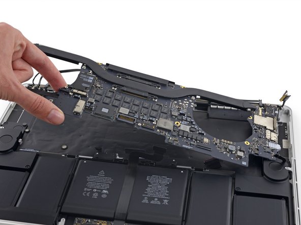
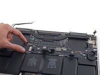
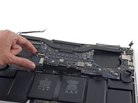
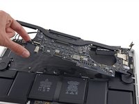
Lift and pull the entire logic board assembly away from the wall of the upper case.
-
-
-
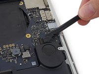
Remove the following screws securing the left speaker to the upper case:
-
2.7 mm T5 Torx screw
-
6.9 mm T5 Torx screw (with 4.5 mm shoulder)
-
5.6 mm T5 Torx screw
-
-
-
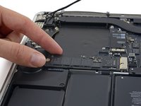
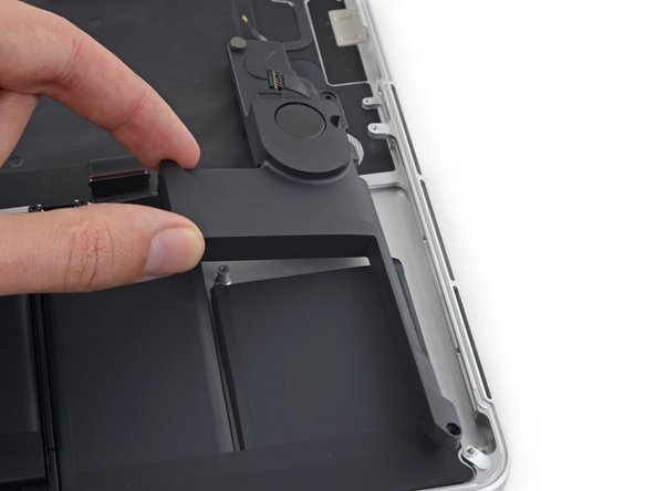
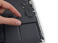
Remove the left speaker by pulling it slightly away from the side of the upper case, and out from under the aluminum tab blocking it in.
-


To reassemble your device, follow these instructions in reverse order.
To reassemble your device, follow these instructions in reverse order.
crwdns2935221:0crwdne2935221:0
crwdns2935229:087crwdne2935229:0

crwdns2947412:018crwdne2947412:0
Hi! Such an excellent guide you’ve made. But I wonder, if I want to replace only the speaker, should I disassemble most of the parts or just doing step 41-42? Because I’m too afraid that I’ll break those small wirings and connectors.. while my only problem is the speaker.
Unfortunately, you must disassemble the whole machine - the board is covering a portion of the speaker and therefore it is impossible to remove with the board still on there.
Hi, I just went through replacing the left speaker and the screen. So much more involved to get to the left speaker than changing the screen.
But the replacement speaker is only giving me highs and not bass. Anyone ran into this issue? could it be a faulty speaker? I bought it here on ifixit. I don’t suppose it is from a bad replacement procedure that I could have done. Either the speaker has sound or it doesn’t?
Thanks.
No, have not noticed a decrease in bass from the replacement speaker. (bought used from eBay) Not that you’d want to disassemble everything again but there does seem to be an air intake opening near the end of the long section of the speaker. Perhaps it’s clogged? Also, the shape of the inner speaker is different on the replacement - original is round and the replacement is hexagon, though they both seem to sound the same.
Same. Replaced 2 speakers— one was low sounding, neither any bass. Returned, replaced again, same issue. At wits end.