crwdns2933423:0crwdne2933423:0

crwdns2931315:0crwdnd2931315:0crwdne2931315:0

crwdns2942213:0crwdne2942213:0

  1. crwdns2935201:0crwdne2935201:0 crwdns2935203:0crwdne2935203:0

    : crwdns2935265:01crwdnd2935265:01crwdnd2935265:01crwdne2935265:0
    • Remove the following P5 pentalobe screws securing the lower case to the MacBook Pro:

    • Eight 3.1 mm

    • Two 2.3 mm

  2. crwdns2935201:0crwdne2935201:0 crwdns2935203:0crwdne2935203:0

    : crwdns2935265:02crwdnd2935265:01crwdnd2935265:02crwdne2935265:0 : crwdns2935265:02crwdnd2935265:02crwdnd2935265:02crwdne2935265:0
    • Lifting from the edge nearest the clutch cover, lift the lower case off the MacBook Pro.

  3. crwdns2935201:0crwdne2935201:0 crwdns2935203:0crwdne2935203:0

    : crwdns2935265:03crwdnd2935265:01crwdnd2935265:03crwdne2935265:0 : crwdns2935265:03crwdnd2935265:02crwdnd2935265:03crwdne2935265:0 : crwdns2935265:03crwdnd2935265:03crwdnd2935265:03crwdne2935265:0
    • The lower case has two plastic pegs (red) that fit into plastic clips in the upper case (orange).

    • During reassembly, gently push down the center of the lower case to reattach the case to its two plastic clips.

  4. crwdns2935201:0crwdne2935201:0 crwdns2935203:0crwdne2935203:0

    : crwdns2935265:04crwdnd2935265:01crwdnd2935265:01crwdne2935265:0
    • Peel back the sticker covering the battery connector.

  5. crwdns2935201:0crwdne2935201:0 crwdns2935203:0crwdne2935203:0

    : crwdns2935265:05crwdnd2935265:01crwdnd2935265:03crwdne2935265:0 : crwdns2935265:05crwdnd2935265:02crwdnd2935265:03crwdne2935265:0 : crwdns2935265:05crwdnd2935265:03crwdnd2935265:03crwdne2935265:0
    • Gently lift each side of the battery connector to pry the connector out of its socket on the logic board.

    • Bend the connector back toward the battery, ensuring that the battery connector doesn't accidentally make contact with the logic board.

  6. crwdns2935201:0crwdne2935201:0 crwdns2935203:0crwdne2935203:0

    : crwdns2935265:06crwdnd2935265:01crwdnd2935265:03crwdne2935265:0 : crwdns2935265:06crwdnd2935265:02crwdnd2935265:03crwdne2935265:0 : crwdns2935265:06crwdnd2935265:03crwdnd2935265:03crwdne2935265:0
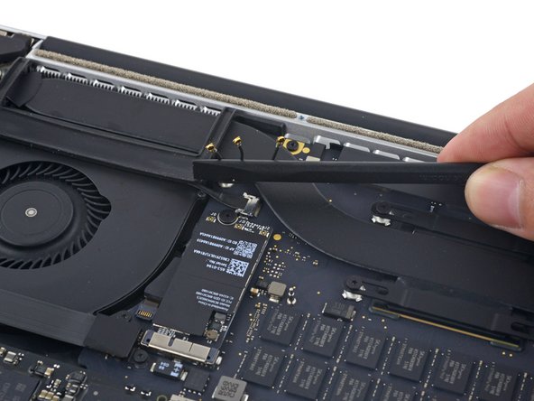
    • Use a spudger or tweezers to pry the three AirPort antenna cables straight up off of their sockets on the AirPort board, and bend them up and out of the way.

    • The cable connection points are very fragile. Be careful to lift only on the connector, and not on the socket or cable.

    • To reconnect, align the connector carefully into position over the socket, and press it down firmly with the flat of your spudger.

  7. crwdns2935201:0crwdne2935201:0 crwdns2935203:0crwdne2935203:0

    : crwdns2935265:07crwdnd2935265:01crwdnd2935265:02crwdne2935265:0 : crwdns2935265:07crwdnd2935265:02crwdnd2935265:02crwdne2935265:0
    • Peel the right rubber cover up off the fan and fold it out of the way.

  8. crwdns2935201:0crwdne2935201:0 crwdns2935203:0crwdne2935203:0

    : crwdns2935265:08crwdnd2935265:01crwdnd2935265:02crwdne2935265:0 : crwdns2935265:08crwdnd2935265:02crwdnd2935265:02crwdne2935265:0
    • Use the tip of a spudger to push the camera cable connector out of its socket on the logic board.

    • Be sure to push parallel to the board, pushing first on one side, then the other to "walk" the connector out of its socket.

  9. crwdns2935201:0crwdne2935201:0 crwdns2935203:0crwdne2935203:0

    : crwdns2935265:09crwdnd2935265:01crwdnd2935265:03crwdne2935265:0 : crwdns2935265:09crwdnd2935265:02crwdnd2935265:03crwdne2935265:0 : crwdns2935265:09crwdnd2935265:03crwdnd2935265:03crwdne2935265:0
    • Use your fingers to pull the AirPort/Camera cables up off the fan.

    • The cables are adhered to the fan, so peel them up carefully to avoid damaging them.

    • Carefully de-route the cables from the plastic cable guide.

    • On reassembly, there should be enough adhesive still on these cables to stick them back down to the fan.

  10. crwdns2935201:0crwdne2935201:0 crwdns2935203:0crwdne2935203:0

    : crwdns2935265:010crwdnd2935265:01crwdnd2935265:01crwdne2935265:0
    • Remove the four 2.2 mm T5 Torx screws securing the I/O board cable connector covers.

  11. crwdns2935201:0crwdne2935201:0 crwdns2935203:0crwdne2935203:0

    : crwdns2935265:011crwdnd2935265:01crwdnd2935265:02crwdne2935265:0 : crwdns2935265:011crwdnd2935265:02crwdnd2935265:02crwdne2935265:0
    • Remove the left connector cover.

    • Use the flat end of a spudger to pry the left end of the I/O board cable up from its socket on the logic board.

  12. crwdns2935201:0crwdne2935201:0 crwdns2935203:0crwdne2935203:0

    : crwdns2935265:012crwdnd2935265:01crwdnd2935265:02crwdne2935265:0 : crwdns2935265:012crwdnd2935265:02crwdnd2935265:02crwdne2935265:0
    • Remove the right connector cover.

    • Use the flat end of a spudger to pry the right end of the I/O board cable up from its socket on the logic board.

  13. crwdns2935201:0crwdne2935201:0 crwdns2935203:0crwdne2935203:0

    : crwdns2935265:013crwdnd2935265:01crwdnd2935265:01crwdne2935265:0
    • Peel the I/O board cable up from the adhesive securing it to the fan.

    • Remove the cable.

  14. crwdns2935201:0crwdne2935201:0 crwdns2935203:0crwdne2935203:0

    : crwdns2935265:014crwdnd2935265:01crwdnd2935265:01crwdne2935265:0
    • Use a T5 Torx driver to remove the following three screws securing the right fan to the logic board:

    • One 5.0 mm screw with a 2.0 mm long shoulder

    • One 4.0 mm screw with a wide head

    • One 4.4 mm screw

  15. crwdns2935201:0crwdne2935201:0 crwdns2935203:0crwdne2935203:0

    : crwdns2935265:015crwdnd2935265:01crwdnd2935265:03crwdne2935265:0 : crwdns2935265:015crwdnd2935265:02crwdnd2935265:03crwdne2935265:0 : crwdns2935265:015crwdnd2935265:03crwdnd2935265:03crwdne2935265:0
    • Use the tip of a spudger to flip up the retaining flap on the right fan ribbon cable ZIF socket.

    • Be sure you are prying up on the hinged retaining flap, not the socket itself.

  16. crwdns2935201:0crwdne2935201:0 crwdns2935203:0crwdne2935203:0

    : crwdns2935265:016crwdnd2935265:01crwdnd2935265:02crwdne2935265:0 : crwdns2935265:016crwdnd2935265:02crwdnd2935265:02crwdne2935265:0
    • Lift the fan and push it gently towards the back edge of the MacBook to free the fan cable from its socket.

    • The fan cable may be adhered to the logic board—to avoid tearing the cable, gently peel it up while lifting the fan.

    • Remove the fan.

  17. crwdns2935201:0crwdne2935201:0 crwdns2935203:0crwdne2935203:0

    : crwdns2935265:017crwdnd2935265:01crwdnd2935265:01crwdne2935265:0
    • Remove the single 2.9 mm T5 Torx screw securing the SSD to the logic board.

  18. crwdns2935201:0crwdne2935201:0 crwdns2935203:0crwdne2935203:0

    : crwdns2935265:018crwdnd2935265:01crwdnd2935265:03crwdne2935265:0 : crwdns2935265:018crwdnd2935265:02crwdnd2935265:03crwdne2935265:0 : crwdns2935265:018crwdnd2935265:03crwdnd2935265:03crwdne2935265:0
    • Lift the end of the SSD up enough to pass over the speaker directly behind it.

    • Do not lift the SSD too high, or you could damage the contacts or socket.

    • Pull the SSD straight out of its socket on the logic board.

  19. crwdns2935201:0crwdne2935201:0 crwdns2935203:0crwdne2935203:0

    : crwdns2935265:019crwdnd2935265:01crwdnd2935265:03crwdne2935265:0 : crwdns2935265:019crwdnd2935265:02crwdnd2935265:03crwdne2935265:0 : crwdns2935265:019crwdnd2935265:03crwdnd2935265:03crwdne2935265:0
    • Use the point of a spudger to flip up the locking mechanism on the I/O board connector.

    • Flip the spudger around and use the flat end to slide the I/O cable out of the connector.

    • Push on the opened locking mechanism for an easy way to slide the I/O cable out of the connector. This could help prevent accidental damage to the cable or connector contacts.

  20. crwdns2935201:0crwdne2935201:0 crwdns2935203:0crwdne2935203:0

    : crwdns2935265:020crwdnd2935265:01crwdnd2935265:01crwdne2935265:0
    • Remove the two 3.1 mm T5 Torx screws from the I/O board.

  21. crwdns2935201:0crwdne2935201:0 crwdns2935203:0crwdne2935203:0

    : crwdns2935265:021crwdnd2935265:01crwdnd2935265:02crwdne2935265:0 : crwdns2935265:021crwdnd2935265:02crwdnd2935265:02crwdne2935265:0
    • Slightly lift the interior edge of the I/O board and pull it toward the center of the MacBook, away from the side of the case.

    • Remove the I/O board.

crwdns2935217:0crwdne2935217:0

crwdns2935229:014crwdne2935229:0

Andrew Optimus Goldheart

crwdns2935283:010/17/09crwdne2935283:0

502.807 crwdns2915208:0crwdne2915208:0

crwdns2935297:0407crwdne2935297:0

crwdns2915084:0crwdne2915084:0

iFixit crwdns2935289:0iFixitcrwdne2935289:0

Staff

crwdns2931471:0135crwdne2931471:0

crwdns2935297:016.767crwdne2935297:0

crwdns2917034:0crwdne2917034:0

Be _VERY_ careful with the connector on the end of the I/O cable. Especially since it abuts to the speaker. It is easy to insert it diagonally but that could break the edge pins on the connector. Step 19 of this job (and the inverse) needs at least three hands.

Bryan Lunt - crwdns2934203:0crwdne2934203:0

crwdns2917038:0crwdne2917038:0

crwdns2936625:0crwdne2936625:0:

crwdns2936751:024crwdne2936751:0 8

crwdns2936753:07crwdne2936753:0 57

crwdns2936753:030crwdne2936753:0 176

crwdns2942667:0crwdne2942667:0 23,802