crwdns2915892:0crwdne2915892:0
Use this guide to replace the upper case assembly.
crwdns2942213:0crwdne2942213:0
-
-
Remove the following P5 pentalobe screws securing the lower case to the MacBook Pro:
-
Eight 3.0 mm
-
Two 2.3 mm
-
-
-
Lifting from the edge nearest the clutch cover, lift the lower case off the MacBook Pro.
-
Set the lower case aside.
-
-
-
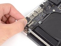
Peel back the warning label covering the battery connector.
-
-
-
Using the flat end of a spudger, gently pry the battery connector straight up out of its socket on the logic board.
-
Bend the battery cables back and out of the way, ensuring that the battery connector doesn't accidentally make contact with the logic board.
-
-
crwdns2935267:0crwdne2935267:0Tweezers$4.99
-
Use a spudger or tweezers to pry the three AirPort antenna cables straight up off of their sockets on the AirPort board.
-
-
-
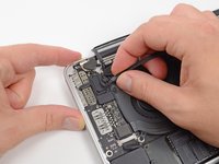
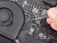
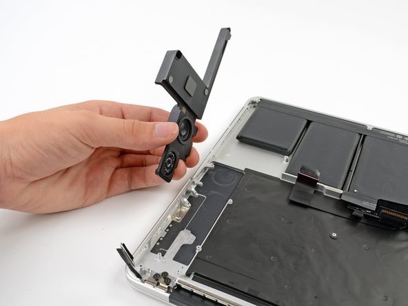
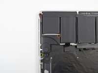
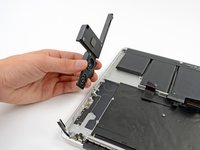
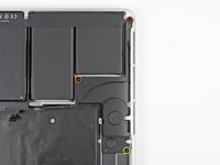
Use the tip of a spudger to push the camera cable's plug toward the fan and out of its socket on the logic board.
-
-
-
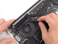
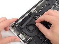
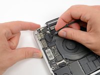
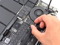
Insert the flat end of a spudger underneath the rubber heat sink cover on the right fan.
-
Slide the spudger underneath the length of the cover, releasing the adhesive.
-
Lift the cover and flip it back so that you can access the cables underneath.
-
-
-
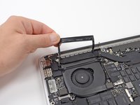
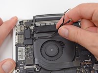
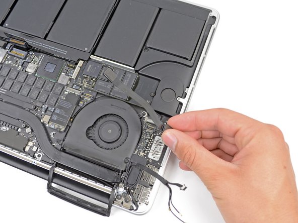
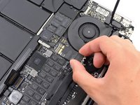
Use your fingers to pull the AirPort/Camera cables up off the fan.
-
Carefully de-route the cables from the plastic cable guide.
-
-
-
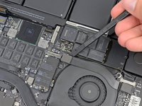
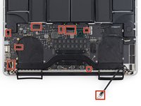
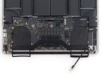
Use the flat end of a spudger to pry the rubber hinge covers up off the left and right hinges.
-
-
-
Remove the two 3.1 mm T5 Torx screws securing the aluminum hinge covers to the upper case.
-
Remove the two aluminum hinge brackets from the MacBook Pro.
-
-
-
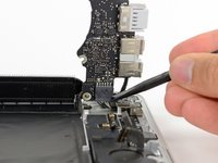
Using the flat end of a spudger, pry the I/O Board connector straight up out of its socket on the logic board.
-
In a similar fashion, remove the I/O Board cable connector from its socket on the I/O Board.
-
Remove the I/O Board cable from the MacBook Pro.
-
-
-
Remove the single 2.9 mm T5 Torx screw securing the AirPort card to the logic board.
-
-
-
Grasp the sides of the AirPort card and lift it up to a shallow angle (5-10˚) to separate the light adhesive adhering it to the logic board.
-
Pull the AirPort card parallel out of its connector on the logic board to remove it.
-
-
-
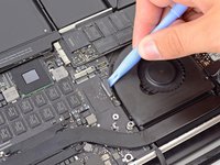
Use the tip of a spudger to flip up the retaining flap on the right fan ribbon cable ZIF socket.
-
Starting at the top of the cable, slide a plastic opening tool under the right fan cable to free it from the logic board.
-
-
-
-
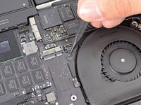
Remove the following three screws securing the right fan to the logic board:
-
One 4.4 mm T5 Torx screw
-
One 3.9 mm T5 Wide Head Torx screw
-
One 5.0 mm T5 Torx screw with 2 mm collar
-
-
-
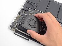
Lift and remove the right fan out from the MacBook Pro.
-
-
-
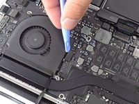
Use the flat end of a spudger to lift the rubber heat sink cover up off the left fan.
-
-
-
Remove the following three screws securing the left fan to the logic board:
-
One 4.4 mm T5 Torx screw with 2 mm collar
-
One 5.0 mm T5 Torx screw with 2 mm collar
-
One 3.9 mm T5 Wide Head Torx screw
-
-
-
Use the tip of a spudger to flip up the retaining flap on the left fan ribbon cable ZIF socket.
-
Starting at the top of the cable, slide a plastic opening tool under the left fan cable to free it from the logic board.
-
Lift the left fan out of the device.
-
-
-
Remove the single 3.1 mm T5 Torx screw securing the SSD to the logic board.
-
-
-
Slightly lift the rightmost side of the SSD and firmly slide it straight away out of its socket on the logic board.
-
-
-
Use the tip of a spudger to flip up the I/O board data cable lock and rotate it toward the battery side of the computer.
-
Use the flat end of a spudger to slide the I/O board data cable straight out of its socket on the logic board.
-
-
-
Remove the two 3.1 mm T5 Torx screws securing the I/O board to the logic board.
-
On some models, also removing the silver 3.5 mm T5 Torx screw from the heatsink can aid in I/O board removal.
-
Carefully lift the I/O board and remove it from the lower case.
-
-
-
Use the flat end of a spudger to pry the left speaker connector up and out of its socket on the logic board.
-
Use the tip of a spudger to pry the right speaker connector up and out of its socket on the logic board
-
-
-
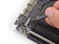
Peel back the tape covering the top of the keyboard ribbon cable connector.
-
Use the flat end of a spudger to flip up the retaining flap on the keyboard ribbon cable ZIF socket.
-
Use the flat end of a spudger to push the keyboard ribbon cable out of its socket.
-
-
-
Use the flat end of a spudger to pry the trackpad ribbon cable connector up out of its socket.
-
-
-
Use the flat end of a spudger to pry the keyboard backlight connector up from its socket on the logic board.
-
-
-
Use the tip of a spudger or your fingernail to flip up the retaining flap on the microphone ribbon cable ZIF socket.
-
Pull the microphone ribbon cable out of its socket.
-
-
-
Use the tip of a spudger to flip up the display data cable lock and rotate it toward the DC-In side of the computer.
-
Pull the display data cable straight out of its socket on the logic board.
-
-
-
Use the flat end of a spudger to carefully pry off the rubber screw cap on the raised screw head near the MagSafe 2 connector.
-
-
-
Remove the following six screws securing the logic board to to the upper case:
-
One 3.1 mm T5 Torx screw
-
One 2.5 mm T5 Torx screw
-
One 5.5 mm silver, raised-head T5 Torx screw
-
Two 5.7 mm T5 Torx screws
-
One 3.8 mm silver T5 Torx screw
-
-
-
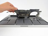
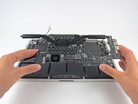
Lifting from the side nearest the battery, rotate the logic board toward the top of the MacBook Pro.
-
Using the flat end of a spudger, carefully push the MagSafe 2 connector out of its socket on the bottom of the logic board.
-
-
-
Remove the logic board assembly from the MacBook Pro.
-
Second photo, clockwise from top: battery, right speaker, keyboard backlight, AirPort/camera, display, microphone, left speaker, keyboard, and trackpad.
-
-
-
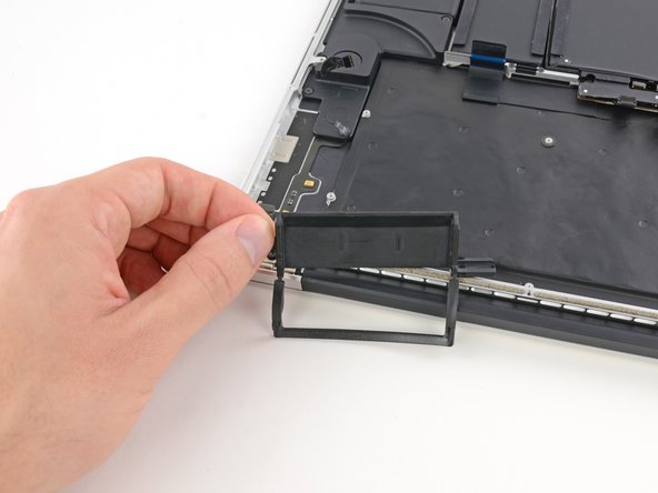
Remove the single 2.6 mm T5 Torx screw securing the left rubber hinge cover in place.
-
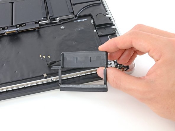
Slide the hinge cover out of its bezel, then lift it up and out of the device.
-
Slide the right cover out of its bezel, then lift it out of the device.
-
-
-
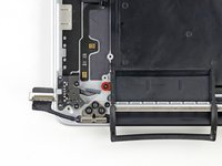
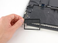
Insert the edge of a plastic opening tool underneath the upper microphone.
-
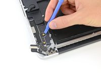
Slide the blade of a plastic opening tool along the bottom of the upper microphone, releasing the adhesive.
-
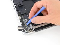
In a similar manner, release the adhesive underneath the lower microphone.
-
Lift the cable out of the device.
-
-
-
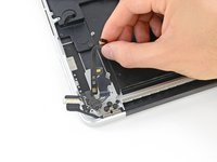
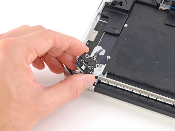
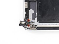
Remove the two 4.0 mm T5 Torx screws securing the MagSafe DC-In board to the upper case.
-
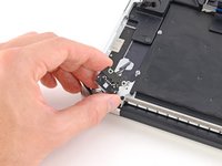
Slide the MagSafe DC-In board towards the right to free it from its recess within the upper case.
-
Lift and remove the MagSafe DC-In board out of the upper case assembly.
-
-
-
Remove the following three screws securing the left speaker to the upper case:
-
One 5.6 mm T5 Torx screw
-
One 6.9 mm T5 Torx screw
-
One 2.6 mm T5 Torx screw
-
Lift the left speaker out of the upper case and set it aside.
-
-
-
Remove the following three screws securing the right speaker to the upper case:
-
One 5.6 mm T5 Torx screw
-
One 6.9 mm T5 Torx screw
-
One 2.6 mm T5 Torx screw
-
Remove the right speaker from the MacBook Pro.
-
-
-
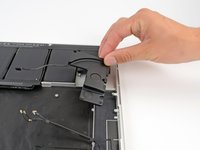
Remove four out of the six 5.3 mm T8 Torx screws securing the display to the upper case.
-
-
-
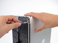
While supporting both halves of the device with one hand, unscrew the upper 5.3 mm T8 Torx screw.
-
-
-
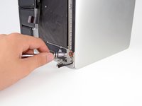
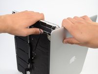
Grip both halves of the device. Firmly put one hand on the top center of the upper case (left) and one in the same place on the display assembly (right).
-
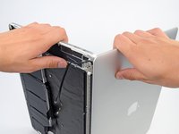
While holding the display assembly in place, slowly push forward on the upper case, releasing it from the display assembly.
-


To reassemble your device, follow these instructions in reverse order.
To reassemble your device, follow these instructions in reverse order.
crwdns2935221:0crwdne2935221:0
crwdns2935229:028crwdne2935229:0

crwdns2947412:08crwdne2947412:0
I want to replace the trackpad, is it difficult to remove the batteries and how ??? please help
I am almost positive you cannot replay the track pad for the retina display models they are covered by the battery and everywhere I have looked it means buying a whole new uppercase. cannot find just the track pad part`
Any instructions for replacing the keyboard?
Great guide! Made it super simple to stay organized and understand what was happening.
One thing I’d like to recommend is that when removing the main board (step 32b), it’s easier to just remove the MagSafe (step 36) at the same time rather than trying to separate the two boards. I understand the separation may have been made to aide in other guides, but if you’re replacing the entire uppercase as I did, it’s definitely easier (and safer) to merge the two.
Once again, an excellent guide. I’ve used it in the past to replace the battery. Today I used it to replace the upper case assembly because of a cracked trackpad. The process took around three hours but I saved over $400 compared to a local Mac repair shop, and who knows how much more if Apple had done it.