crwdns2915892:0crwdne2915892:0
If your MagSafe 2 power adapter has been damaged, you can replace it. Use this guide to install a replacement MagSafe DC-In Board.
crwdns2942213:0crwdne2942213:0
-
-
Remove the following P5 pentalobe screws securing the lower case to the MacBook Pro:
-
Eight 3.0 mm
-
Two 2.3 mm
-
-
-
Lifting from the edge nearest the clutch cover, lift the lower case off the MacBook Pro.
-
Set the lower case aside.
-
-
-
Peel back the warning label covering the battery connector.
-
-
-
Using the flat end of a spudger, gently pry the battery connector straight up out of its socket on the logic board.
-
Bend the battery cables back and out of the way, ensuring that the battery connector doesn't accidentally make contact with the logic board.
-
-
crwdns2935267:0crwdne2935267:0Tweezers$4.99
-
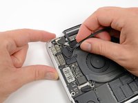
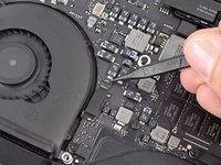
Use a spudger or tweezers to pry the three AirPort antenna cables straight up off of their sockets on the AirPort board.
-
-
-
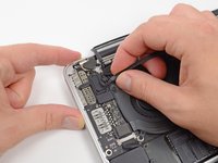
Use the tip of a spudger to push the camera cable's plug toward the fan and out of its socket on the logic board.
-
-
-
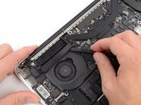
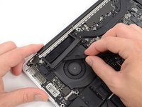
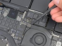
Insert the flat end of a spudger underneath the rubber heat sink cover on the right fan.
-
Slide the spudger underneath the length of the cover, releasing the adhesive.
-
Lift the cover and flip it back so that you can access the cables underneath.
-
-
-
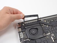
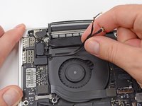
Use your fingers to pull the AirPort/Camera cables up off the fan.
-
Carefully de-route the cables from the plastic cable guide.
-
-
-
Use the flat end of a spudger to pry the rubber hinge covers up off the left and right hinges.
-
-
-
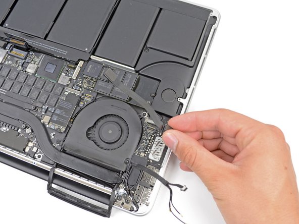
Using the flat end of a spudger, pry the I/O Board connector straight up out of its socket on the logic board.
-
In a similar fashion, remove the I/O Board cable connector from its socket on the I/O Board.
-
Remove the I/O Board cable from the MacBook Pro.
-
-
-
Remove the single 2.9 mm T5 Torx screw securing the AirPort card to the logic board.
-
-
-
-
Grasp the sides of the AirPort card and lift it up to a shallow angle (5-10˚) to separate the light adhesive adhering it to the logic board.
-
Pull the AirPort card parallel out of its connector on the logic board to remove it.
-
-
-
Use the tip of a spudger to flip up the retaining flap on the right fan ribbon cable ZIF socket.
-
Starting at the top of the cable, slide a plastic opening tool under the right fan cable to free it from the logic board.
-
-
-
Remove the following three screws securing the right fan to the logic board:
-
One 4.4 mm T5 Torx screw
-
One 3.9 mm T5 Wide Head Torx screw
-
One 5.0 mm T5 Torx screw with 2 mm collar
-
-
-
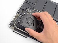
Lift and remove the right fan out from the MacBook Pro.
-
-
-
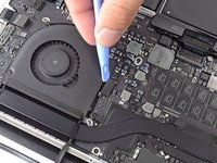
Use the flat end of a spudger to lift the rubber heat sink cover up off the left fan.
-
-
-
Remove the following three screws securing the left fan to the logic board:
-
One 4.4 mm T5 Torx screw with 2 mm collar
-
One 5.0 mm T5 Torx screw with 2 mm collar
-
One 3.9 mm T5 Wide Head Torx screw
-
-
-
Use the tip of a spudger to flip up the retaining flap on the left fan ribbon cable ZIF socket.
-
Starting at the top of the cable, slide a plastic opening tool under the left fan cable to free it from the logic board.
-
Lift the left fan out of the device.
-
-
-
Remove the single 3.1 mm T5 Torx screw securing the SSD to the logic board.
-
-
-
Slightly lift the rightmost side of the SSD and firmly slide it straight away out of its socket on the logic board.
-
-
-
Use the tip of a spudger to flip up the I/O board data cable lock and rotate it toward the battery side of the computer.
-
Use the flat end of a spudger to slide the I/O board data cable straight out of its socket on the logic board.
-
-
-
Remove the two 3.1 mm T5 Torx screws securing the I/O board to the logic board.
-
On some models, also removing the silver 3.5 mm T5 Torx screw from the heatsink can aid in I/O board removal.
-
Carefully lift the I/O board and remove it from the lower case.
-
-
-
Use the flat end of a spudger to pry the left speaker connector up and out of its socket on the logic board.
-
Use the tip of a spudger to pry the right speaker connector up and out of its socket on the logic board
-
-
-
Peel back the tape covering the top of the keyboard ribbon cable connector.
-
Use the flat end of a spudger to flip up the retaining flap on the keyboard ribbon cable ZIF socket.
-
Use the flat end of a spudger to push the keyboard ribbon cable out of its socket.
-
-
-
Use the flat end of a spudger to pry the trackpad ribbon cable connector up out of its socket.
-
-
-
Use the flat end of a spudger to pry the keyboard backlight connector up from its socket on the logic board.
-
-
-
Use the tip of a spudger or your fingernail to flip up the retaining flap on the microphone ribbon cable ZIF socket.
-
Pull the microphone ribbon cable out of its socket.
-
-
-
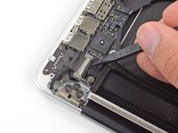
Use the tip of a spudger to flip up the display data cable lock and rotate it toward the DC-In side of the computer.
-
Pull the display data cable straight out of its socket on the logic board.
-
-
-
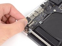
Use the flat end of a spudger to carefully pry off the rubber screw cap on the raised screw head near the MagSafe 2 connector.
-
-
-
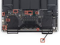
Remove the following six screws securing the logic board to to the upper case:
-
One 3.1 mm T5 Torx screw
-
One 2.5 mm T5 Torx screw
-
One 5.5 mm silver, raised-head T5 Torx screw
-
Two 5.7 mm T5 Torx screws
-
One 3.8 mm silver T5 Torx screw
-
-
-
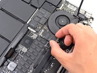
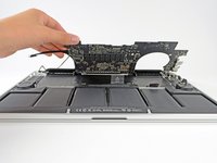
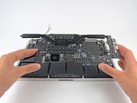
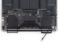
Lifting from the side nearest the battery, rotate the logic board toward the top of the MacBook Pro.
-
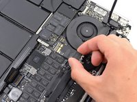
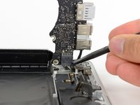
Using the flat end of a spudger, carefully push the MagSafe 2 connector out of its socket on the bottom of the logic board.
-
-
-
Remove the logic board assembly from the MacBook Pro.
-
Second photo, clockwise from top: battery, right speaker, keyboard backlight, AirPort/camera, display, microphone, left speaker, keyboard, and trackpad.
-
-
-
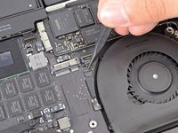
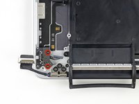
Remove the two 2.5 mm T5 Torx screws securing the MagSafe DC-In board to the upper case.
-
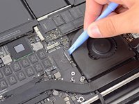
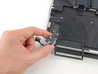
Slide the MagSafe DC-In board towards the right to free it from its recess within the upper case.
-
Lift and remove the MagSafe DC-In board out of the upper case assembly.
-


To reassemble your device, follow these instructions in reverse order.
To reassemble your device, follow these instructions in reverse order.
crwdns2935221:0crwdne2935221:0
crwdns2935229:024crwdne2935229:0

crwdns2947412:012crwdne2947412:0
I have a 820-3332 logic board (late 2013 MBP 15" Retina, same as this how-to) ) that is missing the socket on the underside of the logic board the magsafe board's wired connection slides into on the underside of the logic board as shown in the final steps. I can't find any mention of a new one anywhere. Looks like it was glued on at the factory. So I'm sitting here with a brand new magsafe 2 board with no way to attach it to the logic board. I though of soldering it directly to the pins that the socket mounts up against on the logic board but there are six pins on the logic board and five wires going to five connection points inside the connector that slides into the socket on the board. Looking at the six pin holes in the new magsafe 2 board connector from the top I see three wires, an empty pin hole and then two wires so I wouldn't even know which pins to attach to which board.
Anyone have any suggestions for this mess?
Any suggestions?
Wow! Somewhat complicated to get that DC board out. Wondering if I should even attempt this.
I have a liquid-damaged (coffee) MBP of this vintage. If I plug in the power adapter, the machine boots and runs fine; however, it shows the battery is "not available" in the battery menu and, when I unplug the magsafe adapter, the machine immediately powers off. As the logic board seems to work fine when plugged in, what do you think about attempting to stick in a DC board? Or is that battery "not available" message an indicator that the battery is also hosed? I don't see any obvious damage to the battery (but...).
Thanks for any advice.
This guide is very good and simple to follow. It may seem tricky but it really isn’t, just take your time to unscrew everything and place them in labeled bins, so you can remember where each screw goes.
I had a bit of trouble with the logic board, after everything was unscrewed it took some fiddling around to finally get the logic board to release and lift up.
Great tutorial.
Great guide! Easier than it looked at first glance!
Great, thank you. I got a 20 euro MagSafe board and it works perfectly.
The guide is accurate, and it is indeed easier than I expected.
For reassembly though I had to take out the logic board twice again because one of the small connectors ‘stayed behind’ the logic board and I only discovered later.
So a tip is to count the connectors you removed, and count again to make sure all are in place to connect and didn't stay in an unreachable place before you reattach the logic board.
Also as another tip, for easier reassembly, I put all the screws (and some parts) on the adhesive tape so they stayed in place and I could spatially fix them. I glued the tape to a paper sheet so I could take notes at which step the screws belonged and also other notes.