crwdns2915892:0crwdne2915892:0
Did your laptop go for an accidental swim? Logic board fried? Use this guide to install a new logic board in your MacBook Pro 15" Retina Display Early 2013.
crwdns2942213:0crwdne2942213:0
-
-
Remove the following P5 pentalobe screws securing the lower case to the MacBook Pro:
-
Eight 3.0 mm
-
Two 2.3 mm
-
-
-
Lifting from the edge nearest the clutch cover, lift the lower case off the MacBook Pro.
-
Set the lower case aside.
-
-
-
Peel back the warning label covering the battery connector.
-
-
-
Using the flat end of a spudger, gently pry the battery connector straight up out of its socket on the logic board.
-
Bend the battery cables back and out of the way, ensuring that the battery connector doesn't accidentally make contact with the logic board.
-
-
crwdns2935267:0crwdne2935267:0Tweezers$4.99
-
Use a spudger or tweezers to pry the three AirPort antenna cables straight up off of their sockets on the AirPort board.
-
-
-
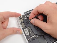
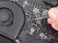
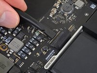
Use the tip of a spudger to push the camera cable's plug toward the fan and out of its socket on the logic board.
-
-
-
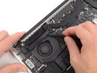
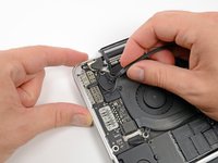
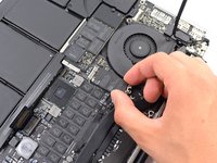
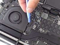
Insert the flat end of a spudger underneath the rubber heat sink cover on the right fan.
-
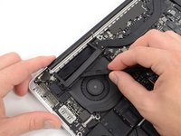
Slide the spudger underneath the length of the cover, releasing the adhesive.
-
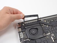
Lift the cover and flip it back so that you can access the cables underneath.
-
-
-
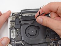
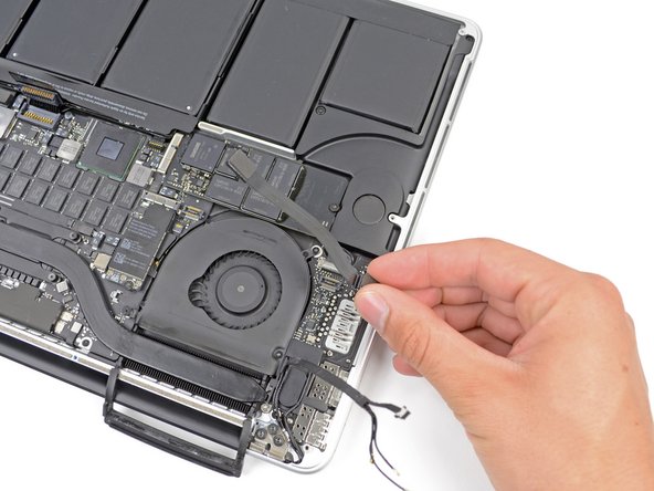
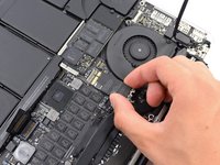
Use your fingers to pull the AirPort/Camera cables up off the fan.
-
Carefully de-route the cables from the plastic cable guide.
-
-
-
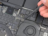
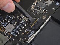
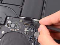
Using the flat end of a spudger, pry the I/O Board connector straight up out of its socket on the logic board.
-
In a similar fashion, remove the I/O Board cable connector from its socket on the I/O Board.
-
Remove the I/O Board cable from the MacBook Pro.
-
-
-
Remove the single 2.9 mm T5 Torx screw securing the AirPort card to the logic board.
-
-
-
Grasp the sides of the AirPort card and lift it up to a shallow angle (5-10˚) to separate the light adhesive adhering it to the logic board.
-
Pull the AirPort card parallel out of its connector on the logic board to remove it.
-
-
-
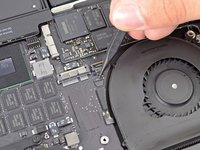
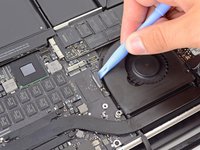
Use the tip of a spudger to flip up the retaining flap on the right fan ribbon cable ZIF socket.
-
Starting at the top of the cable, slide a plastic opening tool under the right fan cable to free it from the logic board.
-
-
-
-
Remove the following three screws securing the right fan to the logic board:
-
One 4.4 mm T5 Torx screw
-
One 3.9 mm T5 Wide Head Torx screw
-
One 5.0 mm T5 Torx screw with 2 mm collar
-
-
-
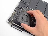
Lift and remove the right fan out from the MacBook Pro.
-
-
-
Use the flat end of a spudger to lift the rubber heat sink cover up off the left fan.
-
-
-
Remove the following three screws securing the left fan to the logic board:
-
One 4.4 mm T5 Torx screw with 2 mm collar
-
One 5.0 mm T5 Torx screw with 2 mm collar
-
One 3.9 mm T5 Wide Head Torx screw
-
-
-
Use the tip of a spudger to flip up the retaining flap on the left fan ribbon cable ZIF socket.
-
Starting at the top of the cable, slide a plastic opening tool under the left fan cable to free it from the logic board.
-
Lift the left fan out of the device.
-
-
-
Remove the single 3.1 mm T5 Torx screw securing the SSD to the logic board.
-
-
-
Slightly lift the rightmost side of the SSD and firmly slide it straight away out of its socket on the logic board.
-
-
-
Use the tip of a spudger to flip up the I/O board data cable lock and rotate it toward the battery side of the computer.
-
Use the flat end of a spudger to slide the I/O board data cable straight out of its socket on the logic board.
-
-
-
Remove the two 3.1 mm T5 Torx screws securing the I/O board to the logic board.
-
On some models, also removing the silver 3.5 mm T5 Torx screw from the heatsink can aid in I/O board removal.
-
Carefully lift the I/O board and remove it from the lower case.
-
-
-
Use the flat end of a spudger to pry the headphone jack connector up from its socket on the logic board.
-
-
-
Use the flat end of a spudger to pry the left speaker connector up and out of its socket on the logic board.
-
Use the tip of a spudger to pry the right speaker connector up and out of its socket on the logic board
-
-
-
Peel back any tape covering the keyboard ribbon cable connector.
-
-
-
Use the flat end of a spudger to flip up the retaining flap on the keyboard ribbon cable ZIF socket.
-
Use the flat end of a spudger to gently back the keyboard ribbon cable out of its socket by pushing first at one side, then the other.
-
-
-
Use the flat end of a spudger to pry the trackpad ribbon cable connector up from its socket on the logic board.
-
-
-
Use the flat end of a spudger to pry the keyboard backlight connector up from its socket on the logic board.
-
-
-
Use the tip of a spudger or your fingernail to flip up the retaining flap on the microphone ribbon cable ZIF socket.
-
Pull the microphone ribbon cable out of its socket.
-
-
-
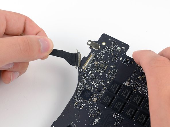
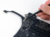
Use the tip of a spudger to pry the display data cable lock and rotate it toward the DC-In side of the computer.
-
Pull the display data cable straight out of its socket on the logic board.
-
-
-
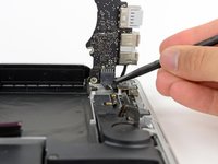
Use the flat end of a spudger to carefully pry off the rubber screw cap on the raised screw head near to the MagSafe 2 connector.
-
-
-
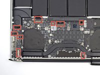
Remove the following six screws securing the logic board to to the upper case:
-
One 2.6 mm T5 Torx screw
-
Two 5.8 mm T5 Torx screws
-
One 3.8 mm T5 Torx screw
-
One 5.2 mm Raised Head T5 Torx screw
-
One 3.5 mm Silver T5 Torx screw
-
-
-
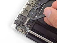
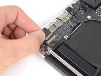
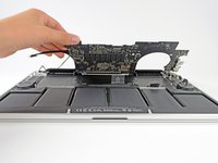
Lifting from the side nearest the battery, rotate the logic board toward the top of the MacBook Pro.
-
Using the flat end of a spudger, carefully push the MagSafe 2 connector out of its socket on the bottom of the logic board.
-
Clockwise from top: keyboard, trackpad, battery, right speaker, keyboard backlight, display, microphone, headphone jack, left speaker.
-
-
-
Remove the logic board assembly from the MacBook Pro.
-
-
-
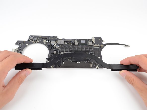
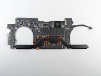
Remove the following eight screws securing the heat sink to the logic board:
-
Two 2.4 mm T5 screws
-
Six 3.4 mm T5 screws
-
Grip both ends of the heat sink and lift it up from the logic board.
-
-
-
Use the tip of a spudger to flip up the metal retaining flap on the HDMI data transfer cable.
-
Gently pull the HDMI data transfer cable straight out of its socket on the logic board.
-


To reassemble your device, follow these instructions in reverse order.
crwdns2935221:0crwdne2935221:0
crwdns2935229:033crwdne2935229:0


crwdns2947412:08crwdne2947412:0
Can I do this same technique with the Late 2013 mac book pro?
Updated recently to High Sierra and now my Logic Board is “broken” per apples Genius Bar. Crashing and restarting unpredictably. Wondering if anyone else has had this problem or if they think replacing the logic board is a potential fix. I’m not new to tearing down or building computers so I’d consider it if I found a good part.
It seems most of the GPU problems in mid 2012/early 2013 15” retina macbook pro models are due to U8900 IC “lead free” soldering.
Some people pointed that resoldering this IC fixed the problem.
https://www.youtube.com/watch?v=upk1QbGi...
(In the comments for above video, he mentioned that original chip is also working fine)
Just did this and found the hardest part was getting the new board in without ‘loosing’ some cables. I did loose one - the backlighting cable but the the time I discovered that I was in no mood to take things back apart to retrieve it. Worked fine when done but am having a bit of intermittent behavior which I think may be related to a previously replaced SSD card. New one on the way for Monday install.
Thanks for a great, detailed tutorial. Very tedious - good test of patience.