crwdns2915892:0crwdne2915892:0
Use this guide to replace a broken microphone.
crwdns2942213:0crwdne2942213:0
-
-
Remove the following ten screws:
-
Three 14.4 mm Phillips #00 screws
-
Three 3.5 mm Phillips #00 screws
-
Four 3.5 mm shouldered Phillips #00 screws
-
-
-
Use your fingers to pry the lower case away from the body of the MacBook near the vent.
-
Remove the lower case.
-
-
-
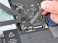
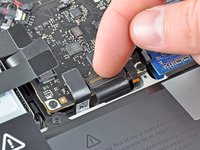
Use the edge of a spudger to pry the battery connector upwards from its socket on the logic board.
-
-
-
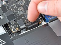
Bend the battery cable slightly away from its socket on the logic board so it does not accidentally connect itself while you work.
-
-
-
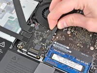
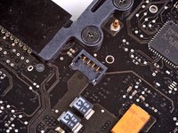
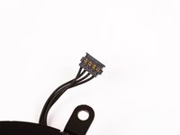
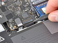
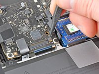
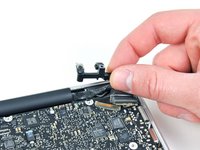
Use the edge of a spudger to gently pry the fan connector up and out of its socket on the logic board.
-
-
-
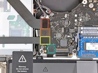
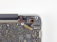
Remove the following three screws securing the fan to the logic board:
-
One 7.2 mm T6 Torx screw
-
Two 5.3 mm T6 Torx screws
-
-
-
Lift the fan out of its recess in the logic board, minding its cable that may get caught.
-
-
-
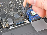
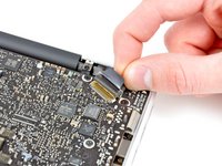
Use the tip of a spudger to pull the right speaker/subwoofer cable out from under the retaining finger molded into the upper case.
-
Pull the right speaker/subwoofer cable upward to lift the connector out of its socket on the logic board.
-
-
-
-
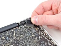
Disconnect the camera cable from the logic board.
-
-
-
Disconnect the following four cables:
-
AirPort/Bluetooth cable
-
Optical drive cable
-
Hard drive cable
-
Trackpad cable
-
-
-
Use your fingernail to flip up the retaining flap on the keyboard ribbon cable ZIF socket.
-
Use the tip of a spudger to pull the keyboard ribbon cable out of its socket.
-
-
-
If present, remove the small strip of black tape covering the keyboard backlight cable socket.
-
-
-
Use the tip of a spudger or your fingernail to flip up the retaining flap on the keyboard backlight ribbon cable ZIF socket.
-
Pull the keyboard backlight ribbon cable out of its socket.
-
-
-
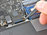
Use the flat end of a spudger to pry the sleep sensor/battery indicator connector up from its socket on the logic board.
-
-
-
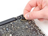
Grab the plastic pull tab secured to the display data cable lock and rotate it toward the DC-In side of the computer.
-
Pull the display data cable straight out of its socket on the logic board.
-
-
-
Remove the following nine screws:
-
Five 3.6 mm T6 Torx screws
-
Two 4.3 mm T6 Torx screws
-
Two 7.2 mm T6 Torx screws
-
Five 3.0 mm T6 screws
-
Two 3.6 mm T6 screws
-
Two 6.7 mm T6 screws
-
-
-
Remove the following two screws:
-
One 8.6 mm Phillips screw
-
One 5.5 mm Phillips screw
-
Remove the display data cable retainer from the upper case.
-
-
-
Use the tip of a spudger to gently peel the microphone off the adhesive securing it to the upper case.
-
-
-
Minding the many connectors near its edges, lift the logic board from the end nearest the optical drive.
-
Without flexing the board, maneuver it out of the upper case, minding the flexible connection to the DC-In board that may get caught in the upper case.
-
Remove the logic board.
-
-
-
De-route the microphone cable from the channel molded into the left speaker housing.
-
-
-
Remove the small piece of black tape covering the microphone connector.
-
-
-
Use the flat end of a spudger to pry the microphone connector up from its socket on the logic board.
-
-
-
Remove the microphone from the logic board.
-


To reassemble your device, follow these instructions in reverse order.
To reassemble your device, follow these instructions in reverse order.
crwdns2935221:0crwdne2935221:0
crwdns2935229:018crwdne2935229:0

crwdns2947412:02crwdne2947412:0
The instructions say, in order to reassemble, just reverse the steps. However, they do not say what adhesive to use for the microphone, or how to properly position it against the frame. Is Barge's Cement adequate?
Extraordinario tutorial, es tan bueno que evita equivocaciones, gracias.