crwdns2915892:0crwdne2915892:0
Replace a broken AirPort card to regain Wi-Fi connectivity.
crwdns2942213:0crwdne2942213:0
-
-
Remove the following 10 screws securing the lower case to the MacBook Pro 13" Unibody:
-
Seven 3 mm Phillips screws.
-
Three 13.5 mm Phillips screws.
-
-
-
Slightly lift the lower case and push it toward the rear of the computer to free the mounting tabs.
-
-
-
Use the flat end of a spudger to lift the battery connector up out of its socket on the logic board.
-
-
-
Use the flat end of a spudger to pry the subwoofer/right speaker cable connector up off its socket on the logic board.
-
-
-
Disconnect the camera cable by sliding it horizontally out of its socket.
-
If you see a small plastic retainer stuck to the logic board that prevents the camera cable from sliding out, peel it up carefully from the logic board. Apply a little heat from a hair dryer or heat gun if necessary to help soften the adhesive holding it in place. Do not attempt to forcibly disconnect the cable with the retainer in place.
-
If you still have trouble, use the point of a spudger to push at each side of the connector and "walk" it slowly from its socket.
-
-
-
De-route the camera data cable from the channel in the optical drive.
-
-
-
Remove the following screws securing the camera data cable and right speaker to the upper case:
-
Two 8 mm Phillips screws.
-
One 4mm Phillips screw.
-
Slide the camera cable bracket out from under the subwoofer and remove it from the computer.
-
-
-
Grab the plastic pull tab secured to the display data cable lock and rotate it toward the DC-in side of the computer.
-
Pull the display data cable connector straight away from its socket.
-
-
-
-
Remove the following two screws securing the display data cable bracket to the upper case:
-
One 7 mm Phillips screw.
-
One 5 mm Phillips screw.
-
Lift the display data cable bracket out of the upper case.
-
-
-
Use your Torx driver to remove the two outer 6.5 mm screws securing each of the two display brackets to the upper case (4 screws total).
-
-
-
Open your MacBook so the display is perpendicular to the upper case.
-
Place your opened MacBook on a table as pictured.
-
While holding the display and upper case together with your left hand, use your Torx driver to remove the remaining 6.5 mm screw from the lower display bracket.
-
-
-
Remove the last remaining 6 mm Torx screw securing the display to the upper case.
-
-
-
Grab the upper case with your right hand and rotate it slightly toward the top of the display so the upper display bracket clears the edge of the upper case.
-
Rotate the display slightly away from the upper case.
-
-
-
Lift the display up and away from the upper case, minding any brackets or cables that may get caught.
-
-
-
Grab the clutch cover as shown and slide it toward the right side of the display.
-
-
-
Gently rock the clutch cover back and forth on its long axis while pulling it away from the display.
-
Do this action along the length of the clutch cover until you can lift it off the framework attaching it to the display.
-
-
-
Remove the clutch cover from the display.
-
-
-
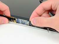
Use the tip of a spudger to pry both AirPort antenna connectors out of their sockets on the AirPort board.
-
-
-
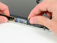
Remove the single 3 mm Phillips screw securing the AirPort card to the display nearest the AirPort antenna.
-
-
-
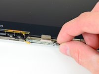
Remove the single 3.3 mm Phillips screw securing the camera cable retainer to the display.
-
-
-
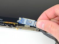
Orient your display as shown and pull the black plastic camera cable retainer toward the right side of the display.
-
Remove the camera cable retainer.
-
-
-
Carefully pull the camera cable connector toward the right side of the display and out of its socket on the AirPort card.
-
-
-
Remove the remaining 3 mm Phillips screw securing the side of the AirPort card closest to the right clutch hinge.
-
-
-
Pull the AirPort card away from its heat sink and remove it from the display.
-


To reassemble your device, follow these instructions in reverse order.
To reassemble your device, follow these instructions in reverse order.
crwdns2935221:0crwdne2935221:0
crwdns2935229:081crwdne2935229:0

crwdns2947412:05crwdne2947412:0
Hello,
Andrew ...my salute to you. This just worked fine to fix my wifi hardware not installed problem on my Macbook pro (2010 mid). Thank you very much.
Regards,
Abhi
wow. I have done this. You’re not kidding it’s difficult! Hope the damned thing works now! I found the Torxes in step 10 to be 8s and a pice of plastic concealing the said torxes on the RHS. Otherwise a great guide! Thank you very much!
Very good instruction, but I still get „No hardware installed“. Any way to exchange the cable between Airport card and logic board? I‘m afraid no.
I have this problem
Luego de instalar el wifi card sigo teniendo el aviso de no hardware instalado. Cuál es la causa y que debo hacer ?