crwdns2915892:0crwdne2915892:0
Replacing the upper case requires the removal of nearly every component in your MacBook Pro. You will also need to transfer your old trackpad over to your new upper case.
crwdns2942213:0crwdne2942213:0
-
-
Remove the following 10 screws securing the lower case to the MacBook Pro 13" Unibody:
-
Seven 3 mm Phillips screws.
-
Three 13.5 mm Phillips screws.
-
-
-
Slightly lift the lower case and push it toward the rear of the computer to free the mounting tabs.
-
-
-
Use the flat end of a spudger to lift the battery connector up out of its socket on the logic board.
-
-
-
Use a spudger to pry the fan connector out of its seat, and straight up off the logic board.
-
-
-
Remove the following three screws securing the fan to the upper case:
-
One 6.5 mm Phillips.
-
One 5.5 mm Phillips.
-
One 4.5 mm Phillips.
-
-
-
Grab the plastic pull tab secured to the display data cable lock, and rotate it toward the DC-in side of the computer.
-
Pull the display data cable connector straight away from its socket, towards the DC-in side of the computer.
-
-
-
Remove the following two screws securing the display data cable bracket to the upper case:
-
One 7 mm Phillips.
-
One 5 mm Phillips.
-
Lift the display data cable bracket out of the upper case.
-
-
-
Use the flat end of a spudger to pry the subwoofer and right speaker connector up off the logic board.
-
-
-
Pull the camera cable connector toward the optical drive to disconnect it from the logic board.
-
-
-
Use the flat end of a spudger to pry the optical drive, hard drive, and trackpad cable connectors up off the logic board.
-
-
-
Use your fingernail or the tip of a spudger to flip up the cable retaining flap on the ZIF socket for the keyboard ribbon cable.
-
Use your spudger to slide the keyboard ribbon cable out of its socket.
-
-
-
Peel the small strip of black tape off the keyboard backlight ribbon cable socket.
-
-
-
Use the tip of a spudger to flip up the cable retaining flap on the ZIF socket for the keyboard backlight ribbon cable.
-
Use your spudger to slide the keyboard backlight ribbon cable out of its socket.
-
-
-
-
Use the flat end of a spudger to pry the battery indicator cable connector up off the logic board.
-
-
-
Use the tip of a spudger to pry the microphone off the adhesive attaching it to the upper case.
-
-
-
Remove the following screws:
-
Five 3.1 mm Phillips.
-
Two 3.9 mm Phillips.
-
Two 7 mm Phillips from the DC-in board.
-
-
-
Remove the following Tri-point screws securing the battery to the upper case:
-
One 5.5 mm Tri-point screw.
-
One 13.5 mm Tri-point screw.
-
Lift the battery out of the upper case.
-
-
-
Lift the logic board from its left edge and raise it until the ports clear the side of the upper case.
-
Pull the logic board away from the side of the upper case and remove it, minding the DC-in board that may get caught.
-
-
-
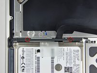
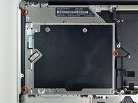
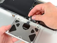
Remove two Phillips screws securing the hard drive bracket to the upper case.
-
Lift the the retaining bracket out from the upper case.
-
-
-
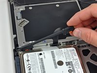
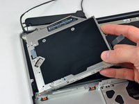
Lift the hard drive from its free edge and pull it out of the chassis, minding the cable attaching it to the computer.
-
-
-
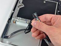
Disconnect the hard drive by pulling the hard drive cable connector away from the drive.
-
-
-
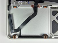
Remove the following four screws securing the hard drive and IR sensor cable to the upper case:
-
Two 1.5 mm Phillips screws.
-
Two 4 mm Phillips screws.
-
Slide the hard drive and IR sensor bracket away from the edge of the upper case.
-
Carefully peel the hard drive and IR sensor cable from the upper case.
-
-
-
Remove the two Phillips screws securing the subwoofer to the upper case.
-
Lift the subwoofer off the optical drive, and set it above the computer.
-
-
-
Remove the two 9.2 mm Phillips screws securing the camera cable bracket to the upper case.
-
Lift the camera cable bracket out of the upper case.
-
-
-
Remove the three 2.5 mm Phillips screws securing the optical drive to the upper case.
-
Lift the optical drive from its right edge and pull it out of the computer.
-
-
-
Peel back the small piece of black tape covering the right speaker cable.
-
-
-
Use the tip of a spudger to pry the right speaker up off the adhesive securing it to the upper case.
-
-
-
Lift the subwoofer and right speaker assembly out of the upper case.
-
-
-
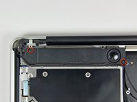
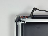
Remove the two outer 6 mm Torx screws securing each side of the display bracket to the upper case (4 screws total).
-
-
-
Open your MacBook so the display is perpendicular to the upper case.
-
Place your opened MacBook on a table as pictured.
-
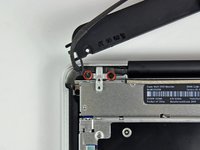
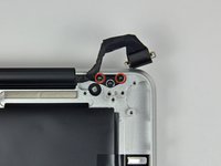
While holding the display and upper case together with your left hand, remove the 6 mm Torx screw from the lower display bracket.
-
-
-
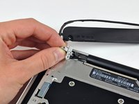
Remove the last remaining 6 mm Torx screw securing the display to the upper case.
-
-
-
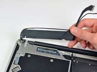
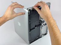
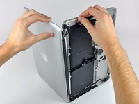
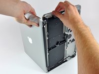
Grab the upper case with your right hand and rotate it slightly toward the top of the display so the upper display bracket clears the edge of the upper case.
-
Rotate the display slightly away from the upper case.
-
Lift the display up and away from the upper case, minding any brackets or cables that may get caught.
-
-
-
Remove the four 1.2 mm Phillips screws highlighted in red.
-
-
-
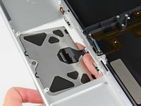
Carefully dislodge the edge of the trackpad closest to the keyboard from its recess in the upper case by pushing it away from the brackets attached to the upper case.
-
De-route the trackpad cable through its slot cut into the upper case.
-
-
-
Pull the trackpad away from the outer edge of the upper case.
-
Remove the trackpad and set it aside.
-
-
-
Use a T6 Torx screwdriver to loosely install the 1.1 mm set screw included with your new upper case into its tapped hole near the middle of the trackpad opening on your new upper case.
-
-
-
Carefully insert the cable from your old trackpad through its slot cut into your new upper case.
-
Use one hand to hold the trackpad cable in place as you insert the two retaining tabs on the outer edge of the trackpad under the lip on the upper case.
-
Pull the trackpad cable as you seat the trackpad into its void in your new upper case.
-
-
-
Insert a 1.2 mm Phillips screw into each of the outer holes drilled into the trackpad (two screws total).
-
-
-
While continually trying to click your trackpad, gently tighten the T6 Torx set screw until the clicks return to their factory "feel."
-
-
-
Next, flip your upper case over so the keyboard side is facing up.
-
Align the trackpad so it is centered in its hole cut into the upper case.
-
-
-
Tighten the outer two screws along the inner edge of the trackpad and check the alignment of it on the outer side of the upper case.
-
If its alignment looks good, install the rest of the Phillips screws along the inner edge of the trackpad.
-
Before reassembling your machine, verify that the set screw is still installed in a position so the mouse will click correctly.
-


To reassemble your device, follow these instructions in reverse order.
To reassemble your device, follow these instructions in reverse order.
crwdns2935221:0crwdne2935221:0
crwdns2935229:048crwdne2935229:0

crwdns2947412:02crwdne2947412:0
Very good tutorial. Guide was 100% accurate. As mentioned, make sure you have good quality tools, and follow the guide to be certain the right get tool is used for certain screws, I did strip one screw head, in my opinion not bad considering all the tiny screws! But now my MacBook works, and save me having to spend on a new MacBook!
Outstanding level of detail!!! Spot on directions.