crwdns2915892:0crwdne2915892:0
Restore balanced sound to your laptop by replacing the left speaker.
crwdns2942213:0crwdne2942213:0
-
-
Remove the following 10 screws securing the lower case to the MacBook Pro 13" Unibody:
-
Seven 3 mm Phillips screws.
-
Three 13.5 mm Phillips screws.
-
-
-
Slightly lift the lower case and push it toward the rear of the computer to free the mounting tabs.
-
-
-
Use the flat end of a spudger to lift the battery connector up out of its socket on the logic board.
-
-
-
Use a spudger to pry the fan connector out of its seat, and straight up off the logic board.
-
-
-
Remove the following three screws securing the fan to the upper case:
-
One 6.5 mm Phillips.
-
One 5.5 mm Phillips.
-
One 4.5 mm Phillips.
-
-
-
Grab the plastic pull tab secured to the display data cable lock, and rotate it toward the DC-in side of the computer.
-
Pull the display data cable connector straight away from its socket, towards the DC-in side of the computer.
-
-
-
Remove the following two screws securing the display data cable bracket to the upper case:
-
One 7 mm Phillips.
-
One 5 mm Phillips.
-
Lift the display data cable bracket out of the upper case.
-
-
-
-
Use the flat end of a spudger to pry the subwoofer and right speaker connector up off the logic board.
-
-
-
Pull the camera cable connector toward the optical drive to disconnect it from the logic board.
-
-
-
Use the flat end of a spudger to pry the optical drive, hard drive, and trackpad cable connectors up off the logic board.
-
-
-
Use your fingernail or the tip of a spudger to flip up the cable retaining flap on the ZIF socket for the keyboard ribbon cable.
-
Use your spudger to slide the keyboard ribbon cable out of its socket.
-
-
-
Peel the small strip of black tape off the keyboard backlight ribbon cable socket.
-
-
-
Use the tip of a spudger to flip up the cable retaining flap on the ZIF socket for the keyboard backlight ribbon cable.
-
Use your spudger to slide the keyboard backlight ribbon cable out of its socket.
-
-
-
Use the flat end of a spudger to pry the battery indicator cable connector up off the logic board.
-
-
-
Use the tip of a spudger to pry the microphone off the adhesive attaching it to the upper case.
-
-
-
Remove the following screws:
-
Five 3.1 mm Phillips.
-
Two 3.9 mm Phillips.
-
Two 7 mm Phillips from the DC-in board.
-
-
-
Remove the following Tri-point screws securing the battery to the upper case:
-
One 5.5 mm Tri-point screw.
-
One 13.5 mm Tri-point screw.
-
Lift the battery out of the upper case.
-
-
-
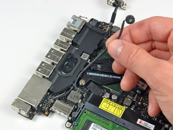
Lift the logic board from its left edge and raise it until the ports clear the side of the upper case.
-
Pull the logic board away from the side of the upper case and remove it, minding the DC-in board that may get caught.
-
-
-
Peel the tape off covering the microphone cable connector.
-
-
-
Use the flat end of a spudger to pry the microphone cable connector up off the logic board.
-
Deroute the microphone cable from the channel in the left speaker.
-
-
-
Remove the strip of tape covering the left speaker cable connector.
-
-
-
Use the flat end of a spudger to pry the left speaker connector up off the logic board.
-
-
-
Carefully peel the left speaker assembly off the adhesive securing it to the logic board.
-


To reassemble your device, follow these instructions in reverse order.
To reassemble your device, follow these instructions in reverse order.
crwdns2935221:0crwdne2935221:0
crwdns2935229:09crwdne2935229:0

crwdns2947412:02crwdne2947412:0
Hallo Walter, kannst Du mir bitte verraten welche A Nummer hat hier aufgeführten MAC?
Hallo Olga, dieses MacBook hat die Nummer A 1278.