crwdns2915892:0crwdne2915892:0
Use this guide to replace a broken front display glass panel. Removal of the front display glass is required to access the LCD.
crwdns2942213:0crwdne2942213:0
-
-
Remove the following 10 screws securing the lower case to the MacBook Pro 13" Unibody:
-
Seven 3 mm Phillips screws.
-
Three 13.5 mm Phillips screws.
-
-
-
Slightly lift the lower case and push it toward the rear of the computer to free the mounting tabs.
-
-
-
Use the flat end of a spudger to lift the battery connector up out of its socket on the logic board.
-
-
-
Use the flat end of a spudger to pry the subwoofer/right speaker cable connector up off its socket on the logic board.
-
-
-
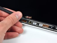
Disconnect the camera cable by sliding it horizontally out of its socket.
-
If you see a small plastic retainer stuck to the logic board that prevents the camera cable from sliding out, peel it up carefully from the logic board. Apply a little heat from a hair dryer or heat gun if necessary to help soften the adhesive holding it in place. Do not attempt to forcibly disconnect the cable with the retainer in place.
-
If you still have trouble, use the point of a spudger to push at each side of the connector and "walk" it slowly from its socket.
-
-
-
De-route the camera data cable from the channel in the optical drive.
-
-
-
Remove the following screws securing the camera data cable and right speaker to the upper case:
-
Two 8 mm Phillips screws.
-
One 4mm Phillips screw.
-
Slide the camera cable bracket out from under the subwoofer and remove it from the computer.
-
-
-
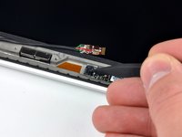
Grab the plastic pull tab secured to the display data cable lock and rotate it toward the DC-in side of the computer.
-
Pull the display data cable connector straight away from its socket.
-
-
-
-
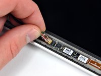
Remove the following two screws securing the display data cable bracket to the upper case:
-
One 7 mm Phillips screw.
-
One 5 mm Phillips screw.
-
Lift the display data cable bracket out of the upper case.
-
-
-
Use your Torx driver to remove the two outer 6.5 mm screws securing each of the two display brackets to the upper case (4 screws total).
-
-
-
Open your MacBook so the display is perpendicular to the upper case.
-
Place your opened MacBook on a table as pictured.
-
While holding the display and upper case together with your left hand, use your Torx driver to remove the remaining 6.5 mm screw from the lower display bracket.
-
-
-
Remove the last remaining 6 mm Torx screw securing the display to the upper case.
-
-
-
Grab the upper case with your right hand and rotate it slightly toward the top of the display so the upper display bracket clears the edge of the upper case.
-
Rotate the display slightly away from the upper case.
-
-
-
Lift the display up and away from the upper case, minding any brackets or cables that may get caught.
-
-
-
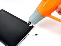
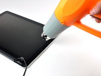
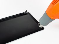
With the heat gun set to low, start by heating the outer black border near the upper right corner of the glass panel.
-
-
crwdns2935267:0crwdne2935267:0Heavy-Duty Suction Cups (Pair)$14.95
-
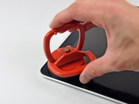
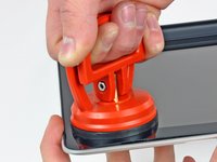
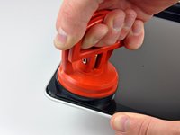
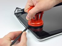
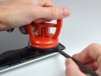
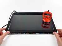
With the panel sufficiently heated, fasten a heavy-duty suction cup near the upper right corner of the display glass.
-
Slowly and gently pull the corner of the display glass up off the display assembly.
-
-
-
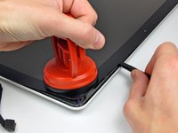
Gently lift the corner of the display glass enough to insert a spudger between it and the display assembly.
-
Use the flat end of a spudger to gently pry up the adhesive securing the front glass to the display.
-
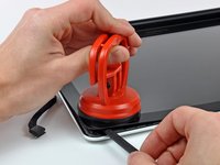
Pry up the glass panel a few inches away from the upper right corner along the top and right edges of the display.
-
-
-
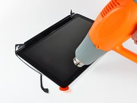
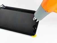
Use a heat gun to soften the adhesive under the black strip along the right side of the front glass panel.
-
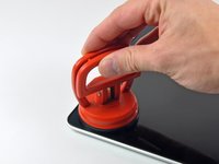
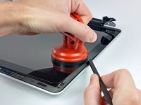
Attach a suction cup along the right side of the front glass panel.
-
Pull up on the glass panel while you use the flat end of a spudger to separate it from the rest of the display assembly.
-
Continue working along the right edge of the front display glass until it is separated from the display.
-
-
-
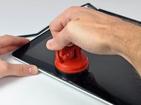
Use your heat gun to soften the adhesive under the black strip along the top edge of the glass display panel.
-
Attach a suction cup near the top edge of the glass display panel and use it to pull the glass panel up off the display.
-
Work along the top edge of the glass panel, carefully using the flat end of a spudger to separate the adhesive if necessary.
-
-
-
Use a heat gun to soften the adhesive under the black strip near the upper left corner of the glass display panel.
-
Attach a suction cup near the upper left corner of the glass display panel.
-
Pull up on the suction cup and use the flat end of a spudger to carefully pry the glass display panel out of the display assembly.
-
-
-
Use a heat gun or hair dryer to soften the adhesive under the black strip along the left side of the front glass panel.
-
Attach a suction cup along the left side of the front glass panel.
-
Pull up on the glass panel while you use the flat end of a spudger to separate it from the rest of the display assembly.
-
Continue working along the left edge of the front display glass until it is separated from the display.
-
-
-
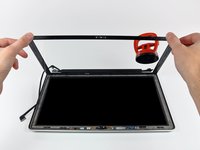
Now that the top, left, and right edges of the glass are free from the display, slowly lift the top edge of the glass panel and gently rotate it out of the display.
-
-
-
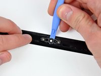
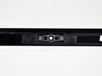
Insert the edge of a plastic opening tool between the display glass and the camera bracket, and run it around the camera bracket to separate it from the display glass.
-
-
-
To reconnect the cable, first use the tip of a spudger to remove the piece of foam tape over the camera cable ZIF socket.
-
Use the tip of a spudger to flip up the ZIF cable retainer on the camera cable socket.
-
Insert the camera cable into its socket on the camera board and use the tip of a spudger to snap down the ZIF cable retainer, locking the cable in place.
-


To reassemble your device, follow these instructions in reverse order.
To reassemble your device, follow these instructions in reverse order.
crwdns2935221:0crwdne2935221:0
crwdns2935229:052crwdne2935229:0

crwdns2947410:01crwdne2947410:0
This guide needs to be replicated / linked on to all the other A1286 13-inch Unibody models as it was done with the 2010 model. The screens are the same for each year of the A1286 generation from 2009, 2010, early 2011, late 2011, and 2012.
Ideally, it could be really helpful if the staff team can improve the article; improve on the steps outlined; using the feedback received in the comments - e,g, safer ways to handle broken glass, use of solvents like alcohol or acetone to dissolve / neutralise the adhesive seal, and ways to preserve the rubber lining, the LCD panel itself, and the additional circuitry & cabling underneath.