crwdns2915892:0crwdne2915892:0
Use this guide to completely replace the logic board.
crwdns2942213:0crwdne2942213:0
-
-
Remove the following ten screws:
-
Three 14.4 mm Phillips #00 screws
-
Three 3.5 mm Phillips #00 screws
-
Four 3.5 mm shouldered Phillips #00 screws
-
-
-
Use your fingers to pry the lower case away from the body of the MacBook near the vent.
-
Remove the lower case.
-
-
-
Use the edge of a spudger to pry the battery connector upwards from its socket on the logic board.
-
-
-
Bend the battery cable slightly away from its socket on the logic board so it does not accidentally connect itself while you work.
-
-
-
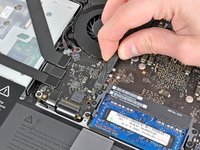
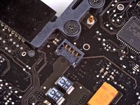
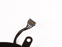
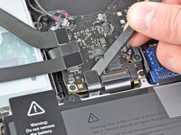
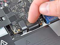
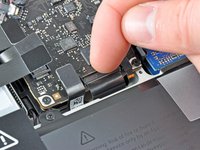
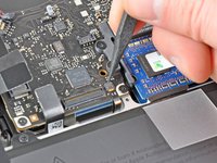
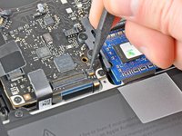
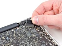
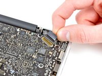
Use the edge of a spudger to gently pry the fan connector up and out of its socket on the logic board.
-
-
-
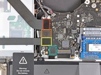
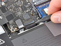
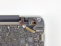
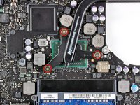
Remove the following three screws securing the fan to the logic board:
-
One 7.2 mm T6 Torx screw
-
Two 5.3 mm T6 Torx screws
-
-
-
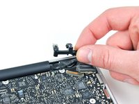
Lift the fan out of its recess in the logic board, minding its cable that may get caught.
-
-
-
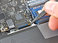
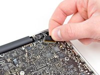
Use the tip of a spudger to pull the right speaker/subwoofer cable out from under the retaining finger molded into the upper case.
-
Pull the right speaker/subwoofer cable upward to lift the connector out of its socket on the logic board.
-
-
-
Disconnect the camera cable from the logic board.
-
-
-
Disconnect the following four cables:
-
AirPort/Bluetooth cable
-
Optical drive cable
-
Hard drive cable
-
Trackpad cable
-
-
-
-
Use your fingernail to flip up the retaining flap on the keyboard ribbon cable ZIF socket.
-
Use the tip of a spudger to pull the keyboard ribbon cable out of its socket.
-
-
-
If present, remove the small strip of black tape covering the keyboard backlight cable socket.
-
-
-
Use the tip of a spudger or your fingernail to flip up the retaining flap on the keyboard backlight ribbon cable ZIF socket.
-
Pull the keyboard backlight ribbon cable out of its socket.
-
-
-
Use the flat end of a spudger to pry the sleep sensor/battery indicator connector up from its socket on the logic board.
-
-
-
Grab the plastic pull tab secured to the display data cable lock and rotate it toward the DC-In side of the computer.
-
Pull the display data cable straight out of its socket on the logic board.
-
-
-
Remove the following nine screws:
-
Five 3.6 mm T6 Torx screws
-
Two 4.3 mm T6 Torx screws
-
Two 7.2 mm T6 Torx screws
-
Five 3.0 mm T6 screws
-
Two 3.6 mm T6 screws
-
Two 6.7 mm T6 screws
-
-
-
Remove the following two screws:
-
One 8.6 mm Phillips screw
-
One 5.5 mm Phillips screw
-
Remove the display data cable retainer from the upper case.
-
-
-
Use the tip of a spudger to gently peel the microphone off the adhesive securing it to the upper case.
-
-
-
Minding the many connectors near its edges, lift the logic board from the end nearest the optical drive.
-
Without flexing the board, maneuver it out of the upper case, minding the flexible connection to the DC-In board that may get caught in the upper case.
-
Remove the logic board.
-
-
-
De-route the microphone cable from its slot molded into the left speaker enclosure.
-
-
-
Remove the small piece of black tape covering the left speaker connector.
-
-
-
Use the flat end of a spudger to pry the left speaker connector up from its socket on the logic board.
-
-
-
Carefully pry the left speaker off the foam adhesive securing it to the logic board.
-
Remove the left speaker.
-
-
-
Remove the piece of black tape covering the microphone connector.
-
-
-
Pull the microphone cable upward to lift its connector out of the socket on the logic board.
-
Remove the microphone.
-
-
-
Pull the MagSafe DC-In board cable toward the heat sink to disconnect it from the logic board.
-
Remove the DC-In board.
-
-
-
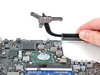
Remove the three 8.4 mm #1 Phillips screws securing the heat sink to the logic board.
-
Carefully remove the heat sink from the processor.
-
-
-
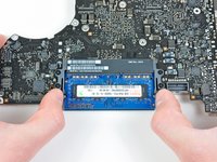
Pull the two RAM retaining arms away from the center of the RAM chip.
-
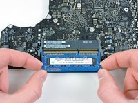
Pull the RAM stick out of its socket.
-
Logic board remains.
-


To reassemble your device, follow these instructions in reverse order.
crwdns2935221:0crwdne2935221:0
crwdns2935229:0133crwdne2935229:0

crwdns2947412:06crwdne2947412:0
My son spilled soda into 13"MB early 2011, I did not get to repair for 6 weeks. Machine took over twice typical time to start-up and once running, cursor showed stuttered movement and launching applications was very slow.
I used guide (only steps 1-19) to remove logic board and delicately cleaned with very slightly damp Q-Tip (using Windex electronics cleaner) & dried, every place I cleaned, using compressed air. I did not remove the heatsink, as I assumed the paste protected the processor underneath.
Once cleaned, I reversed all steps and it booted quickly and all other issues disappeared. THANK YOU!!!
what is logic board part number if I want to order new one
For the Early 2011 MBP A1278 with the Core i5 2.3 GHz processor, the part numbers are 661-5869 and 661-6078
Susanna -
Do you send to Brazil the same Logic board above Its the Early 2011 MBP A1278 with the Core i5 2.3 GHz processo. It had many issues with it’s Logic boar and I think it’s a manufacture defect. I’m so desaposentes with apple planned Obsolescence, ando no repair. It’s not the same apple. My computer was boutique inAustralia , so I’m protected by their consumer act(2010) I just have to prove it was a hidden problem.
My track pad was difficult to "click". I've replaced batteries before, so I knew that it was definitely a swollen battery. However, when removing the damaged, swollen battery, I used the end of a flat head screw driver to pry up the battery connection... DON'T DO THAT! I saw the tiniest of sparks around pins 4-5-6 on the 9 pin battery connector. New battery installed, but the OS didn't recognize the new battery -- black "X" over the battery indicator. Further, the wall charger would not recharge the new battery. Instead, the computer ran off the 30% charge that new batteries are shipped with. I ordered another new battery, and after draining a second battery without being able to charge, I figured that spark was the sign that I fried something in the logic board. Indeed that was exactly the case, and logic board replacement did fix the issue. I found these instructions INVALUABLE in replacing my old logic board.
$260 lesson: Always use a plastic spudger when dislodging connectors in computers!
Thanks!