crwdns2915892:0crwdne2915892:0
Use this guide to replace a faulty logic board.
Don't forget to follow our thermal paste application guide before you reinstall your heat sink.
crwdns2942213:0crwdne2942213:0
-
crwdns2935267:0crwdne2935267:0Magnetic Project Mat$19.95
-
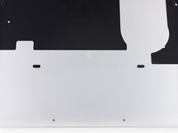
Remove the following ten screws securing the lower case to the upper case:
-
Two 2.3 mm P5 Pentalobe screws
-
Eight 3.0 mm P5 Pentalobe screws
-
-
-
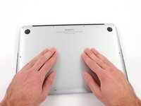
Wedge your fingers between the upper case and the lower case.
-
Gently pull the lower case away from the upper case to remove it.
-
-
-
Use the flat end of a spudger to lift the battery connector straight up out of its socket on the logic board.
-
-
-
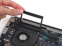
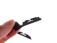
Carefully remove the rubber fan bumper from the edge of the heat sink.
-
-
-
Use the flat end of a spudger to peel the four foam stickers off of the heat sink screws.
-
-
-
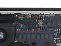
Remove the following screws securing the heat sink to the logic board:
-
One 2.7 mm T5 screw (silver)
-
Four T5 screws (black)
-
-
-
Remove the heat sink from the laptop.
-
-
-
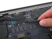
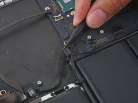
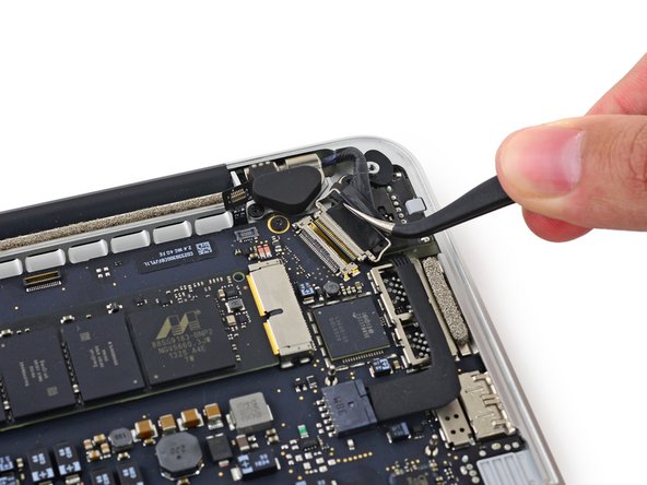
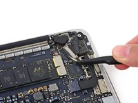
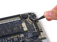
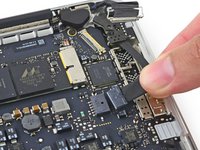
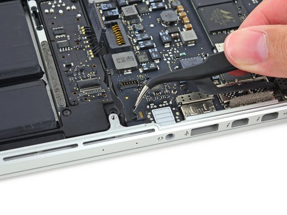
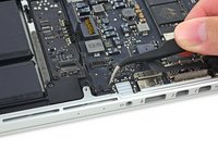
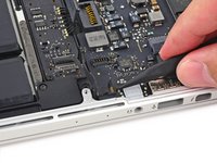
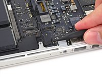
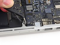
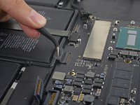
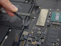
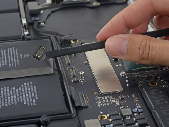
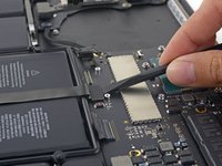
Use the tip of a spudger to push on either side of the the iSight camera cable connector to walk it out of its socket on the logic board.
-
-
-
-
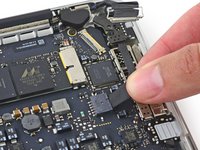
Peel the iSight camera cable off the fan housing to fold it out of the way.
-
-
-
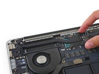
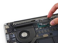
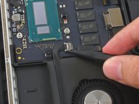
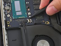
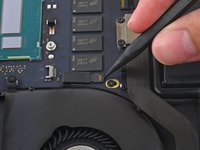
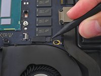
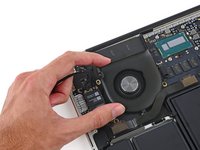
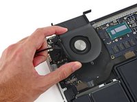
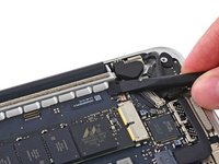
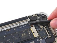
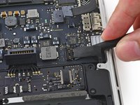
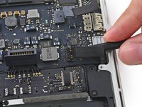
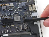
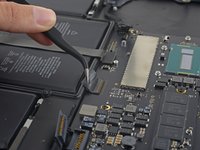
Use the tip of a spudger to flip the tab on the fan's ZIF connector.
-
Carefully pull the fan cable straight out of its socket.
-
-
-
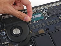
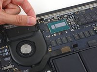
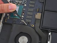
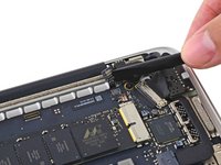
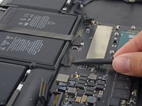
Remove the following screws securing the fan to the upper case:
-
One 5.0 mm T5 Torx screw
-
Two 3.6 mm T5 Torx screws
-
-
-
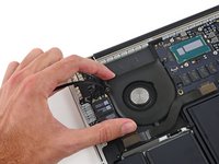
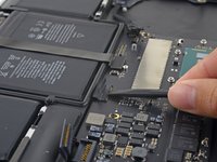
Lift the end of the fan closest to the display hinge and remove the fan from the upper case.
-
-
-
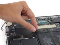
Remove the two 2.1 mm T5 Torx screws securing the I/O board cable bracket to the logic board.
-
Remove the I/O board cable bracket.
-
-
-
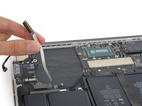
Use the flat end of a spudger to pop the I/O board connector straight up off its socket on the logic board.
-
-
-
Lift the logic board end of the I/O board cable straight up to bend it out of the way.
-
-
-
Use the tip of a spudger to lift the right speaker connector straight up out of its socket on the logic board.
-
-
-
With the tip of a spudger, push on either side of the I/O board connector to walk it out of its socket on the logic board.
-
-
-
Use the flat end of a spudger to disconnect the keyboard backlight cable and bend it up out of the way of the logic board.
-
-
-
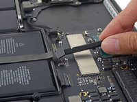
Grab the black plastic tab to flip the display cable connector open and pull it straight out of its socket on the logic board.
-
-
-
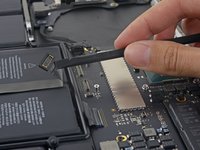
Carefully pull the DC-In board connector straight out of its socket on the logic board.
-
-
-
Wedge the flat end of a spudger under the left speaker cable near the connector and lift it straight up out of its socket and fold it out of the way.
-
-
-
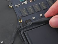
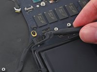
Use the tip of a spudger to flip the retaining tab on the microphone cable ZIF connector.
-
Pull the microphone cable out of its socket on the logic board.
-
-
-
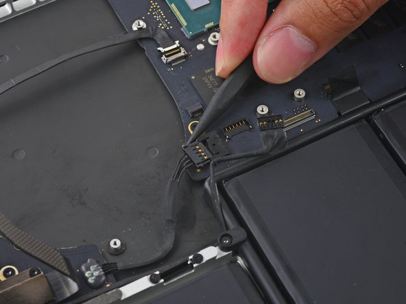
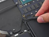
Use the tip of a spudger to flip the retaining tab on the ZIF connector.
-
-
-
Pull the keyboard cable straight out of its ZIF socket on the logic board.
-
-
-
Use the flat end of a spudger to pop the trackpad connector straight up off its socket on the logic board.
-
Fold the cable out back over the battery to clear the way for the logic board.
-
-
-
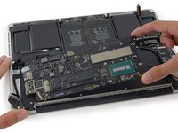
Remove the five 3.5 mm T5 Torx screws securing the logic board to the upper case.
-
-
-
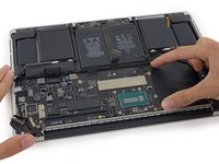
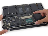
Lift the processor end of the logic board up slightly and pull it toward the fan recess to free the ports from the edge of the upper case.
-
Remove the logic board.
-
-
-
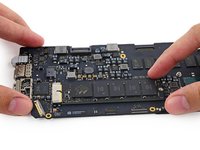
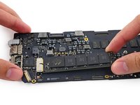
Remove the single 2.9 mm T5 Torx screw securing the SSD to the logic board.
-
-
-
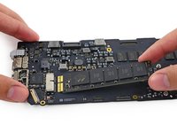
Lift the free end of the SSD up slightly and pull it straight out of its socket on the logic board.
-


To reassemble your device, follow these instructions in reverse order.
crwdns2935221:0crwdne2935221:0
crwdns2935229:0143crwdne2935229:0

crwdns2947412:024crwdne2947412:0
Any idea where the power on pads are ?
Sebastien
I did not need to remove the heat sink. You can simply remove part of the fan assembly in about 1 minute and the heat sink and its associated arm with fins comes right out. Removing the heat sink introduces unnecessary complications that could destroy your logic board should you perform an incorrect repair on the thermal paste.
Any instructions and images demonstrating this?
Richard -
Only part i am missing is how to give the new board it's serial number
me too,me too,