crwdns2915892:0crwdne2915892:0
Use this guide to replace the display assembly.
crwdns2942213:0crwdne2942213:0
-
crwdns2935267:0crwdne2935267:0Magnetic Project Mat$19.95
-
Remove the following ten screws securing the lower case to the upper case:
-
Two 2.3 mm P5 Pentalobe screws
-
Eight 3.0 mm P5 Pentalobe screws
-
-
-
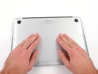
Wedge your fingers between the upper case and the lower case.
-
Gently pull the lower case away from the upper case.
-
Remove the lower case and set it aside.
-
-
-
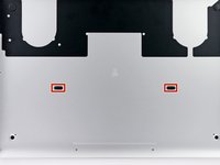
The lower case is connected to the upper case at the center, with two plastic clips.
-
-
-
Remove the plastic cover adhered to the battery contact board.
-
-
-
Remove the following screws securing the battery connector board to the logic board:
-
Two 2.8 mm T6 Torx screws
-
One 7.0 mm T6 Torx shouldered screw
-
-
crwdns2935267:0crwdne2935267:0Tweezers$4.99
-
Use tweezers to remove the small plastic cover located near the bottom right of the battery connector board.
-
-
-
Remove the wide head 6.4 mm T6 Torx screw securing the battery connector to the logic board assembly.
-
-
-
-
Carefully lift the battery connector board up off the logic board.
-
It is recommended to bend the battery cables just slightly, to keep the board suspended up above the logic board and out of the way.
-
-
crwdns2935267:0crwdne2935267:0Tweezers$4.99
-
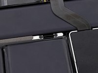
Grasp the Interposer with tweezers.
-
Lift the Interposer off the logic board and remove it.
-
-
-
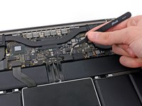
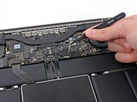
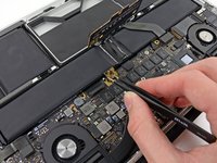
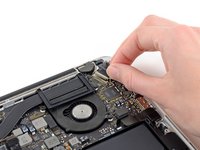
Use the tip of a spudger to push the iSight camera cable connector straight away from its socket on the logic board.
-
-
-
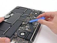
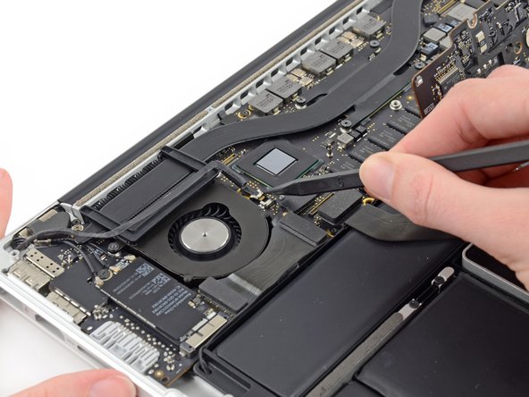
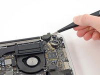
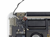
Use the flat end of a spudger to pry and disconnect the three antenna cable connectors from the AirPort board.
-
The three cables are coded with black sleeves of different lengths. During reassembly:
-
Connect the long-sleeved cable to the socket closest to the ports.
-
The short-sleeved cable connects next to the screw.
-
The remaining cable has no sleeve, and connects in the last empty socket, next to the fan.
-
-
-
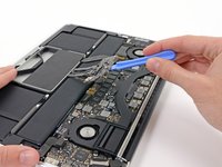
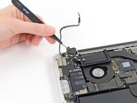
Move the antenna cables aside, clear of the AirPort board.
-
-
-
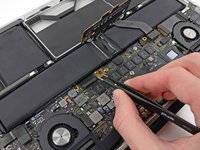
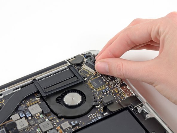
Grab the black pull tab secured to the display data cable lock and rotate it toward the DC-In side of the computer.
-
Pull the display data cable straight out of its socket on the logic board.
-
-
crwdns2935267:0crwdne2935267:0Tweezers$4.99
-
Use a pair of tweezers to lift the rubber hinge covers up off the right and left display hinges.
-
-
-
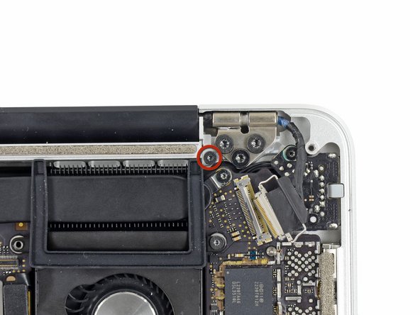
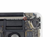
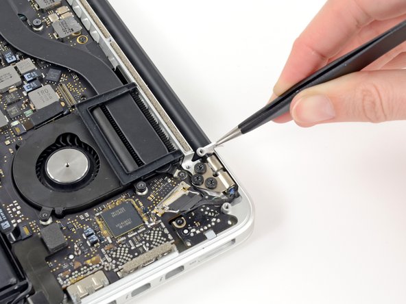
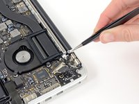
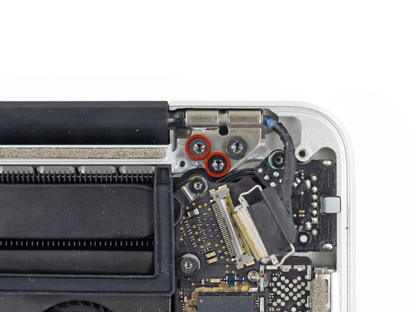
Remove the two 3.1 mm T5 Torx screws securing the aluminum hinge brackets.
-
-
-
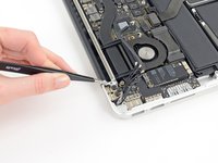
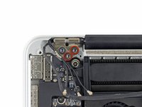
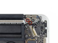
Use a pair of tweezers to lift aluminum hinge brackets off the right and left display hinges.
-
-
-
Remove the four inner 5.3 mm T8 Torx screws (two on each side) securing the display to the upper case.
-
-
-
While holding the display and upper case together with your left hand, remove the remaining T8 Torx screw from the upper display bracket.
-
Remove the last remaining T8 Torx screw securing the display to the upper case.
-
-
-
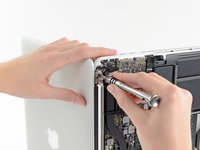
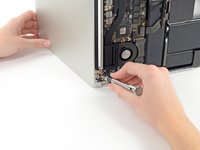
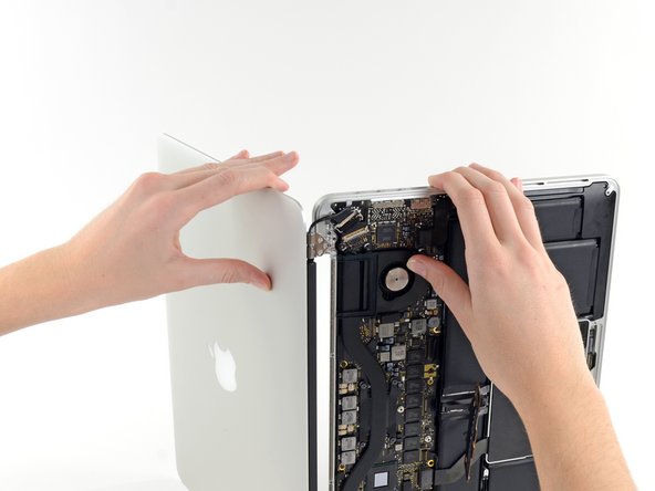
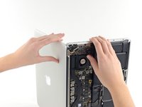
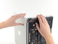
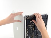
Grip both halves of the device, one in each hand.
-
Gently push forward on the bottom half of the device to detach it from the display assembly.
-
Carefully set each component aside, making sure to set down the lower half keyboard-side down.
-


To reassemble your device, follow these instructions in reverse order.
crwdns2935221:0crwdne2935221:0
crwdns2935229:034crwdne2935229:0


crwdns2947412:08crwdne2947412:0
perfect tutorial! I fixed my screen completely destroyed falling down from my hands while a was falling asleep. Bought a new one on eBay (not original but perfect with the exception of the case slightly different in color and "texture".
Thanks iFix IT!
Ciao
Ciro
This walkthrough/guide is PERFECT! I barely tinker with electronics, but the high cost of repair made me want to try to install a new display assembly myself. Bless you, Sam Lionheart!
This worked really well. The only issue I had was uninstalling the camera. The instructions to pull the data display cable parallel to logic board made sense in step 14. Unfortunately I didn't understand the similarities in step 10. Is it possible to repair the camera now that the slot is completely broken?
Walk through worked perfect. Did it twice. The first time was just to make sure that wasn’t anything disconnect or any wires damage. The second time was to replace the screen. Works perfect.
Hi,
can I replace an damaged display of a MacBook Pro 13” late 2013 with a display from the early 2013 version?
I compared the high-def pictures of each cable connection and they seem to be identical, or am I wrong?
Thanks for the help.
Cheers
L